Variable Frequency Drives & Cooling Towers
By: Doug Smith
ABB Representative
Cooling towers are at the heart of many industrial processes. While tower designs vary from manufacturer to manufacturer, fans are always used to move air through the cooling tower, cooling the process water.
Operating requirements for a cooling tower may include the ability to start and stop the fan, change the fan speed (based on the sump water temperature), and possibly change the fan direction (seasonal – may be temperature and/or climate dependant).
Common application challenges include:
- Brakes or sensors are needed to ensure f
an blades are not rotating in the reverse direction before starting (prevent snapped motor shaft)
- Additional starter(s) or maintenance personnel to swap motor leads for reverse fan operation
- Pitch of the blades may need to be adjusted according to the season (air temperature) to prevent motor overloading due to cold, dense air
- Fan speed control not taken into consideration at system design stage (single speed starter)
- Increased maintenance costs due to power train shock/stresses and motor starter replacement (systems with single and two-speed starters)
- Process water temperatures are not accurately controlled (unstable operation – large swings in fan speed create large temperature swings)
Applying Variable Frequency Drives (VFD’s)…
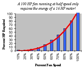
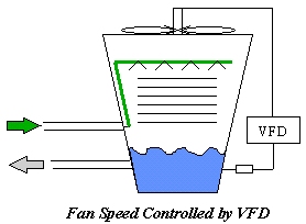
on cooling towers eliminate many drawbacks associated with starter-controlled fans. Reduced energy consumption (lower utility costs), reduced maintenance requirements (personnel & equipment replacement costs) and process water temperature stabilization are among the benefits.
The fan may be spinning when a VFD is commanded to start. A VFD must correctly identify motor rotation, slow the motor down to zero speed (when opposite rotation is detected), accelerate the motor in the correct direction and not trip on an over-voltage or over-current condition.
Mechanical brakes or anti-ratcheting devices can be used to ensure that a fan doesn’t rotate in the wrong direction. A VFD eliminates both mechanical and electrical brakes as well as anti-ratcheting devices, time delay relays, etc.
In extreme cold weather, tower icing can be averted by running the fan slower than required, raising the tower and process water temperatures. It is also common to reverse a cooling tower fan, keeping the heat in the tower. VFD’s accomplish this function & eliminate reversing starters.
Likewise, on hot days, when the air is thinner, fans can be run above 60 Hz, providing additional cooling capacity. The VFD’s current and/or torque limit function will limit the current of the motor such that the nameplate FLA rating is not exceeded. This is impossible without a VFD.
A fan blade’s pitch may be adjusted to minimize cycling between low and high speed (two-speed starter system) and to compensate for winter and summer operation. Often this compromise results in inefficient fan operation.
Fan pitch properly adjusted will increase air flow, provide better cooling, result in further fan speed reductions and increased energy savings.
Starter-controlled fans achieve temperature control by continuously starting and stopping the fan and selecting the speed (if equipped with a two-speed starter).
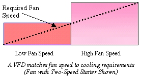
A VFD precisely controls the fan speed, compensating as the outside climate and process loads change,
Retro-fitting Cooling Towers
Existing motors may be installed on a VFD, eliminating single speed and two-speed starters. (A two-speed motor is permanently wired for high speed operation).
A minimum speed of 20 – 25% is usually possible on an existing motor. For direct connected or belted cooling tower fans, this minimum speed is usually not a concern.
However, when a gearbox is used, the minimum speed is more critical, as the gearbox may depend on an internal oil slinger for lubrication. Consult the manufacturer of the cooling tower for minimum speed requirements.
VFD controlled cooling tower fans operate over many speeds as opposed to the fans on a single or two-speed motor starter. As such, it is a good practice to perform a vibration analysis on the fan and tower assembly, as a mechanical resonance may develop at certain speeds.
Identified problem speeds may be programmed into the drive and “locked out”. Vibration switches are often wired into a drive or control system, shutting down the cooling tower if a problem arises.
A drive may also be able to monitor oil level and temperature of the gearbox.
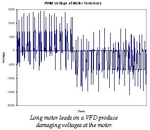
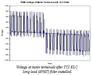
VFD’s are usually not mounted close to the cooling tower, resulting in long lead lengths between the drive and the motor. For older motors with lead lengths greater than 60 feet, a long lead (dV/dT) filter is recommended.
New motors may be approved for VFD operation with motor lead lengths in excess of 350 feet, without the need for an output filter. Consult the motor manufacturer for motor lead length and carrier frequency restrictions.
Well suited for the rigors of an industrial environment, the ACS 800 was designed with maximum reliability in mind. Standard features include 3% impedance AC line reactors. Additionally, capacitor banks and cooling fans have a life expectancy of 100,000 & 60,000 hours respectively.
A wide operating voltage range (380-500 VAC ± 10%) in conjunction with an over-voltage controller, eliminate over-voltage trips. By utilizing the load inertia, an under-voltage controller provides extended ride thru capability.
The common look and feel of the ACS 800 minimizes training requirements as well as helps to keep the cost of spare parts down. The majority of components are the same, regardless of the HP or voltage ratings.

Advanced Flux Optimization yields up to a 10% increase in efficiency at 25% load for additional energy savings.
DTC provides the highest possible starting torque, up to 200% nominal, from a standard AC induction motor. This is better performance than can be achieved across the line.
Standard features of the ACS 800 include a full function PID controller and a 24 VDC power supply. Temperature sensors can be directly wired into the drive. If a speed reference or temperature signal is lost, the ACS 800 may be programmed to go to a preset speed, maintain the last average speed or shut down and indicate a fault.
It is possible to program the ACS 800 such that when the water temperature is below the set point, the ACS 800 will “go-to-sleep”, shutting off the fan. When the temperature rises above the set point, the ACS 800 “wakes”, resuming temperature control. Adjustment of the PID set point is possible via a remote analog signal, serial communication or by direct entry thru the drive keypad.
Industry standard Fieldbus serial communication options allow remote control via a PLC, PC or DCS system. Direct control of speed reference, monitoring of operating data, changing of drive parameters, etc., are possible.
Supported protocols include: Ethernet, Profibus, Modbus, ModbusPlus, ControlNet, DeviceNet, etc. ABB’s flexible communication options enable future control system upgrades, yet protects your VFD investment.
The ACS 800’s capabilities include emulation of Scalar (V/Hz), Sensorless Vector & Vector technologies, but with superior performance. No other drive technology performs as well as ABB’s Direct Torque Control.
Features/Benefits of Variable Frequency Drives
- Improved Power Factor (.98 across speed range)
- Maximize Power Distribution System
- Reduced Inrush Currents
- Minimize Peak Demand Charges
- Soft Start/Soft Stop
- Eliminates Mechanical Shock and Stress on Power Train (couplings, belts, drive shafts, gear boxes, etc.)
- Reduce Utility (Operating) Costs
- Reduced Energy Consumption, Process Operates at Most Efficient Point
- Allows Load Shedding
- May Qualify for Utility Rebates
- Controlled Acceleration and Deceleration
- Eliminates Motor Voltage Imbalance
- Input Power Phase Reversal Protection
Additional Features of ACS 800
- Allows 1000 ft. motor lead lengths, without concern for the drive’s operation or protection.
- Sense Motor Phase Loss (Open Windings)
- Adaptive Programming (PLC Functionality)
- 15 Function Blocks, 20 Functions
- Start-up Assistant (No Manual Required)
- Prompts Automatically Generated based on Drive Status/Options to ease Set-up
- Sense Motor Phase to Phase Short Circuit
- Sense Motor Phase to Ground Short Circuit
- Protection at Start and while Running
- Electronic Motor Overload Protection
- Motor Under/Over Voltage Protection
- Flux Braking provides Highest Possible Braking Torque (without brake chopper & resistor banks)
- Controls and Limits Speed, Current & Torque
- Sense Input Power Single Phase (Phase Loss)
Worlds largest Manufacturer of Variable Frequency Drives
(Fractional-135,000 HP)
24 Months On-Site, Parts & Labor Warranty
(with Certified Start-Up)
Technical Support – 24 Hours x 365 Days/Year
1 800 HELP 365
Many utilities are now offering rebates for the installation of VFD’s or retro-fitting existing equipment with variable frequency drives. Contact your local utility or search VFD rebate or go to the DSIRE website, a comprehensive source of information on state, local, utility and federal incentives and policies that promote renewable energy and energy efficiency.
 Joliet Technologies has partnered with Hudson Energy, in our effects to promote energy efficiency through the use of variable speed drives.


 an blades are not rotating in the reverse direction before starting (prevent snapped motor shaft)