DC DRIVE FUNDAMENTALS
UNDERSTANDING DC DRIVES
Modern DC drives have been available since the early 1970’s. Modern motor drive revolution began with the appearance of microprocessors.
DC motors have been available for nearly 200 years. In fact the first electric motors were designed and built for operation from direct current power. The first commutator DC electric motor capable of turning machinery was invented by British scientist William Sturgeon in 1832.
AC motors are Now and will of course remain the basic prime movers for the fixed speed requirements of industry. Their basic simplicity, dependability and ruggedness make AC motors the natural choice for the vast majority of industrial drive applications.
Then where do DC drives fit into the industrial drive picture of the future?
In order to supply the answer, it is necessary to examine some of the basic characteristics obtainable from DC motors and their associated solid state controls.
- Wide speed range.
- Good speed regulation.
- Compact size and light weight (relative to mechanical variable speed).
- Ease of control.
- Low maintenance.
- Low cost.
In order to realize how a DC drive has the capability to provide the above characteristics, the DC drive has to be analyzed as two elements that make up the package. These two elements are of course the motor and the control. (The “control” is more accurately called the “regulator”).
DC MOTORS
Basic DC motors as used on nearly all packaged drives have a very simple performance characteristic the shaft turns at a speed almost directly proportional to the voltage applied to the armature. Figure 1 shows a typical voltage/speed curve for a motor operating from a 115 volt control.
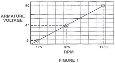
Figure 1 shows a typical voltage/speed curve for a motor operating from a 115 volt control.
From the above curve you can see that with 9 volts applied to the armature, this motor would be operating at Point 1 and turn at approximately 175 RPM. Similarly with 45 volts applied, the motor would be operating at Point 2 on the curve or 875 RPM. With 90 volts applied, the motor would reach its full speed of 1750 RPM at point 3.
From this example a general statement can be made that DC motors have “no load” characteristics that are nearly a perfect match for the curve indicated in Figure 1.
However, when operated at a fixed applied voltage but a gradually increasing torque load, they exhibit a speed droop as indicated in Figure 2.

When operated at a fixed applied voltage but a gradually increasing torque load, they exhibit a speed droop as indicated in Figure 2.
This speed droop is very similar to what would occur if an automobile accelerator pedal was held in a fixed position with the car running on level ground. Upon starting up an incline where more driving torque would be needed, the car would slow down to a speed related to the steepness of the hill. In a real situation, the driver would respond by depressing the accelerator pedal to compensate for the speed loss to maintain a nearly constant speed up the incline.
In the DC drive a similar type of “compensation” is employed in the control to assist in maintaining a nearly constant speed under varying load (torque) conditions.
The measurement of this tendency to slow down is called Regulation and is calculated with the following equation:
|
% Regulation = |
No Load Speed – Full Load Speed |
X 100 |
In DC drives the regulation is generally expressed as a percentage of motor base speed.
If the control (regulator) did not have the capability of responding to and compensating for changing motor loads, regulation of typical motors might be as follows:
| HP | % MOTOR REGULATION | HP | % MOTOR REGULATION |
| 1/4 | 13.6 | 1.5 | 8.0 |
| 1/3 | 12.9 | 2 | 7.2 |
| 1/2 | 13.3 | 3 | 4.2 |
| 3/4 | 10.8 | 5 | 2.9 |
| 1 | 6.7 | 7.5 | 2.3 |
One other very important characteristic of a DC motor should be noted. Armature amperage is almost directly proportional to output torque regardless of speed. This characteristic is shown by Figure 3. Point 1 indicates that a small fixed amount of current is required to turn the motor even when there is no output torque. This is due to the friction of the bearings, electrical losses in the motor materials and load imposed by the air in the motor (windage).

Armature amperage is almost directly proportional to output torque regardless of speed.
Beyond Point 1 through Point 2 and 3, the current increases in direct proportion to the torque required by the load.
From this discussion and Figure 3 a general statement can be made that for PM and Shunt Wound motors load torque determines armature amperage.
In summary, two general statements can be made relative to DC motor performance.
- Motor Speed is primarily determined by Applied Armature Voltage.
- Motor Torque is controlled by Armature Current (amperes).
Understanding these two concepts of DC motors provides the key to understanding total drive performance.
REGULATORS (CONTROLS)
The control provides two basic functions:
- It rectifies AC power converting it to DC for the DC motor.
- It controls the DC output voltage and amperage in response to various control and feedback signals thereby regulating the motor’s performance, both in speed and torque.
RECTIFYING FUNCTION
The basic rectifying function of the control is accomplished by a combination of power semiconductors (Silicon Controlled Rectifiers and Diodes) that make up the “power bridge” assembly.
REGULATING FUNCTION
The regulating function is provided by a relatively simple electronic circuit that monitors a number of inputs and sums these signals to produce a so called “error” signal. This error signal is processed and transformed into precisely timed pulses (bursts of electrical energy). These pulses are applied to the gates of the SCR’s in the power bridge thereby regulating the power output to the DC motor.
For most purposes it is not necessary to understand the electronic details of the regulator, however, in order to appreciate the regulator function it is good to understand some of the input signals that are required to give the regulator its capabilities, these are shown diagrammatically in Figure 4.
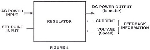
Some of the input signals that are required to give the regulator its capabilities.
The AC to DC power flow is a relatively simple straight through process with the power being converted from AC to DC by the action of the solid state power devices that form the power bridge assembly.
The input and feedback signals need to be studied in more detail.
SET POINT INPUT
In most packaged drives this signal is derived from a closely regulated fixed voltage source applied to a potentiometer. 10 volts is a very common reference.

10 volts is a very common reference.
The potentiometer has the capability of accepting the fixed voltage and dividing it down to any value of from, for example, 10 to zero volts, depending on where it is set. A 10 volt input to the regulator from the speed adjustment control (potentiometer) corresponds to maximum motor speed and zero volts corresponds to zero speed. Similarly any speed between zero and maximum can be obtained by adjusting the speed control to the appropriate setting.
SPEED FEEDBACK INFORMATION
In order to “close the loop” and control motor speed accurately it is necessary to provide the control with a feedback signal related to motor speed.
The standard method of doing this in a simple control is by monitoring the armature voltage and feeding it back into the regulator for comparison with the input “set point” signal.
When armature voltage becomes high, relative to the set point, established by the speed potentiometer setting, an “error” is detected and the output voltage from the power bridge is reduced to lower the motor’s speed back to the “set point”. Similarly when the armature voltage drops an error of opposite polarity is sensed and the control output voltage is automatically increased in an attempt to re-establish the desired speed.
The “Armature Voltage Feedback System” which is standard in most packaged drives is generally called a “Voltage Regulated Drive”.
A second and more accurate method of obtaining the motor speed feedback information is called “Tachometer Feedback”. In this case the speed feedback signal is obtained from a motor mounted tachometer. The output of this tachometer is directly related to the speed of the motor. Using Tachometer Feedback generally gives a drive improved regulation characteristics. When “tach feedback” is used the drive is referred to as a “Speed Regulated Drive”. Most controls are capable of being modified to accept tachometer signals for operation in the tachometer feedback mode.
In some newer high performance “digital drives” the feedback can come from a motor mounted encoder that feeds back voltage pulses at a rate related to motor speed. These (counts) are processed digitally being compared to the “set point” and error signals are produced to regulate the armature voltage and speed.
CURRENT FEEDBACK
The second source of feedback information is obtained by monitoring the motor armature current. As discussed previously, this is an accurate indication of the torque required by the load.
The current feedback signal is used for two purposes:
- As positive feedback to eliminate the speed droop that occurs with increased torque load on the motor. It accomplishes this by making a slight corrective increase in armature voltage as the armature current increases.
- As negative feedback with a “threshold” type of control that limits the current to a value that will protect the power semiconductors from damage. By making this function adjustable it can be used to control the maximum torque the motor can deliver to the load.
The current limiting action of most controls is adjustable and is usually called “Current Limit” or “Torque Limit”.
In summary, the Regulator accomplishes two basic functions:
- It converts the alternating Current to Direct Current.
- It regulates the armature voltage and current to control the speed and torque of the DC Motor.
TYPICAL ADJUSTMENTS
In addition to the normal external adjustment such as the speed potentiometer. there are a number of common internal adjustments that are used on simple small analog type SCR Drives (Silicon Controlled Rectifier Drive). Some of these adjustments are as follows:
- Minimum Speed
- Maximum Speed
- Current Limit (Torque Limit) . IR Compensation
- Acceleration Time . Deceleration Time
The following is a description of the function that these individual adjustments serve and their typical use.
MINIMUM SPEED
In most cases when the control is initially installed the speed potentiometer can be turned down to its lowest point and the output voltage from the control will go to zero causing the motor to stop. There are many situations where this is not desirable. For example there are some machines that want to be kept running at a minimum speed and accelerated up to operating speed as necessary. There is also a possibility that an operator may use the speed potentiometer to stop the motor to work on the machine. This can be a dangerous situation since the motor has only been brought to a stop by zeroing the input signal voltage. A more desirable situation is when the motor is stopped by opening the circuit to the motor or power to the control using the on/off switch. By adjusting the minimum speed up to some point where the motor continues to run even with the speed potentiometer set to its lowest point, the operator must shut the control off to stop the motor. This adds a little safety into the system. The typical minimum speed adjustment is from 0 to 30% of motor base speed.
MAXIMUM SPEED
The maximum speed adjustment sets the maximum speed attainable either by raising the input signal to its maximum point or turning the potentiometer to the maximum point. For example on a typical DC motor the rated speed of the motor might 1750 RPM but the control might be capable of running it up to 1850 or 1900 RPM. In some cases it’s desirable to limit the motor (and machine speed) to something less than would be available at this maximum setting. The maximum adjustment allows this to be done. By turning the internal potentiometer to a lower point the maximum output voltage from the control is limited. This limits the maximum speed available from the motor. In typical controls such as our BC140 the range of adjustment on the maximum speed is from 50 to 110% of motor base speed.
CURRENT LIMIT
One very nice feature of electronic speed controls is that the current going to the motor is constantly monitored by the control. As mentioned previously, the current drawn by the armature of the DC motor is related to the torque that is required by the load. Since this monitoring and control is available an adjustment is provided in the control that limits the output current to a maximum value.
This function can be used to set a threshold point that will cause the motor to stall rather than putting out an excessive amount of torque. This capability gives the motor/control combination the ability to prevent damage that might otherwise occur if higher values of torque were available. This is handy on machines that might become jammed or otherwise stalled. It can also be used where the control is operating a device such as the center winder where the important thing becomes torque rather than the speed. In this case the current limit is set and the speed goes up or down to hold the tension 0 the material being wound. The current limit is normally factory set at 150% of the motor’s rated current. This allows the motor to produce enough torque to start and accelerate the load and yet will not let the current (and torque) exceed 150% of its rated value when running. The range of adjustment is typically from 0 to 200% of the motor rated current.
IR COMPENSATION
IR compensation is a method used to adjust for the droop in a motor’s speed due to armature resistance. As mentioned previously, IR compensation is positive feedback that causes the control output voltage to rise slightly with increasing output current. This will help stabilize the motor’s speed from a no load to full load condition. If the motor happens to be driving a load where the torque is constant or nearly so, then this adjustment is usually unnecessary. However, if the motor is driving a load with a widely fluctuating torque requirement, and speed regulation is critical, then IR compensation can be adjusted to stabilize the speed from the light load to full load condition. One caution is that when IR compensation is adjusted too high it results in an increasing speed characteristic. This means that as the load is applied the motor is actually going to be forced to run faster. When this happens it increases the voltage and current to the motor which in turn increases the motor speed further. If this adjustment is set too high an unstable “hunting” or oscillating condition occurs that is undesirable.
ACCELERATION TIME
The Acceleration Time adjustment performs the function that is indicated by its name. It will extend or shorten the amount of time for the motor to go from zero speed up to the set speed. It also regulates the time it takes to change speeds from one setting (say 50%) to another setting (perhaps 100%). So this setting has the ability to moderate the acceleration rate on the drive.
A couple notes are important: if an acceleration time that is too rapid is called for “acceleration time” will be overridden by the current limit. Acceleration will only occur at a rate that is allowed by the amount of current the control passes through to the motor. Also important to note is that on most small controls the acceleration time is not linear. What this means is that a change of 50 RPM may occur more rapidly when the motor is at low speed than it does when the motor is approaching the set point speed. This is important to know but usually not critical on simple applications where these drives are used.
DECELERATION TIME
This is an adjustment that allows loads to be slowed over an extended period of time. For example, if power is removed from the motor and the load stops in 3 seconds, then the decel time adjustment would allow you’to increase that time and “power down” the load over a period of 4, 5, 6 or more seconds. Note: On a conventional simple DC drive it will not allow for the shortening of the time below the “coast to rest” time.
ADJUSTMENT SUMMARY
The ability to adjust these six adjustments gives great flexibility to the typical inexpensive DC drive. In most cases the factory preset settings are adequate and need not be changed, but on other applications it may be desirable to tailor the characteristics of the control to the specific application.
Many of these adjustments are available in other types of controls, such as variable frequency drives.