Adjustable Speed Drives –
(a.k.a. Variable Speed Drives)
What They Are, How They Work
Application Information
- Adjustable Speed Drives – Application Information
- DC Drives – Principles of Operation
- DC Drive Types
- DC Motor Control Characteristics
- AC Drives – Principles of Operation
- AC Controller Types
- AC Motor Control Characteristics
- Motor Selection
- AC vs. DC Drive Comparison
- Basic Mechanics
- Other Application Factors
- Measuring Machine Torque
- Mechanical Formulas
DC DRIVES – PRINCIPLES OF OPERATION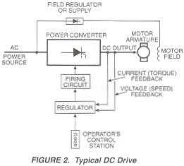
DC drives, because of their simplicity, ease of application, reliability and favorable cost have long been a backbone of industrial applications. A typical adjustable speed drive using a silicon controller rectifier (SCR) power conversion’ section, common for this type unit, is shown in Figure 2. The SCR, (also termed a thyristor) converts the fixed voltage alternating current (AC) of the power source to an adjustable voltage, controlled direct current (DC) output which is applied to the armature of a DC motor.
SCR’s provide a controllable power output by “phase angle control”, so called because the firing angle (a point in time where the SCR is triggered in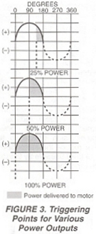 to conduction) is synchronized with the phase rotation of the AC power source. If the device is triggered early in half cycle, maximum power is delivered to the motor; late triggering in the half cycle provides minimum power, as illustrated by Figure 3. The effect is similar to a very high speed switch, capable of being turned on and “conducted” off at an infinite number of points within each half cycle. This occurs at a rate of 60 times a second on a 60 Hz line, to deliver a precise amount of power to the motor. The efficiency of this form of power control is extremely high since a very small amount of triggering energy can enable the SCR (Silicon Controlled Rectifier) to control a great deal of output power.
Adjustable Speed Drive Application Information provided by: FINCOR Automation