Adjustable Speed Drives –
(a.k.a. Variable Speed Drives)
What They Are, How They Work
Application Information
- Adjustable Speed Drives – Application Information
- DC Drives – Principles of Operation
- DC Drive Types
- DC Motor Control Characteristics
- AC Drives – Principles of Operation
- AC Controller Types
- AC Motor Control Characteristics
- Motor Selection
- AC vs. DC Drive Comparison
- Basic Mechanics
- Other Application Factors
- Measuring Machine Torque
- Mechanical Formulas
DC DRIVE TYPES
Nonregenerative DC Drives – Nonregenerative DC drives are the most conventional type in common usage. In their most basic form they are able to control motor speed and torque in one direction only as shown by Quadrant I in Figure 4. The addition of an electromechanical (magnetic) armature reversing contactor or manual switch (units rated 2 HP or less) permits reversing the controller output polarity and therefore the direction of rotation of the motor armature as illustrated in Quadrant III. In both cases torque and rotational direction are the same.
Regenerative DC Drives – Regenerative adjustable speed drives, also known as four-quadrant drives, are capable of controlling not only the speed and direction of motor rotation, but also the direction of motor torque. This is illustrated by Figure 4.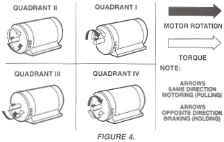
The term regenerative describes the ability of the drive under braking conditions to convert the mechanical energy of the motor and connected load into electrical energy which is returned (or regenerated) to the AC power source.
When the drive is operating in Quadrants I and III, both motor rotation and torque are in the same direction and it functions as a conventional nonregenerative unit. The unique characteristics of a regenerative drive are apparent only in Quadrants II and IV. In these quadrants, the motor torque opposes the direction of motor rotation which provides a controlled braking or retarding force. A high performance regenerative drive, is able to switch rapidly from motoring to braking modes while simultaneously controlling the direction of motor rotation.
A regenerative DC drive is essentially two coordinated DC drives integrated within a common package. One drive operates in Quadrants I and IV, the other operates in Quadrants II and III. Sophisticated electronic control circuits provide interlocking between the two opposing drive sections for reliable control of the direction of motor torque and/or direction of rotation.
Converter Types – The power conversion or rectified power section of a DC drive is commonly called the converter. The individual characteristics of the various converter types used in standard industrial applications have had a definite influence in the design of compatible DC motors as shown in Table 2.
TABLE 1. COMPARISON OF NON-REGENERATIVE VS. REGENERATIVE
DC DRIVE CAPABILITIES
| Nonregenerative | Regenerative | |
| Braking | No inherent braking capability. Requires the addition of a dynamic braking circuit which dissipates the braking energy as heat in a resistor. Braking effort is exponential with initial high torque which reduces to zero at zero speed. Braking circuits are rated for stopping only, not continuous hold back, or as a holding brake. | Inherent electronically by regeneration whereby the knetic energy of the motor and driven machine is restored to the AC power source. Can be regulated to control the braking torque down to, and at zero speed. Typically capable of contonuous braking torque for hold back applications. |
| Reversing | No inherent reversing capability. Requires the addition of reversing contacts or a switch to reverse the polarity of DC voltage applied to the motor. Normally rated for occasional reversing. | An inherent capability. Motor polarity is reversed electronically with no contacts to arc, burn or wear. Desirable for applications requiring frequent reversals. |
| Simplicity | The least complex and least expensive form of electronic adjustable speed motor control. | More complex since it includes double the nonregenerative circuitry. |
| Efficiency and Speed Range | Controller efficiency up to 99%, complete drive with motor 87%. Speed range up to 50:1 without a feedback tachometer, 200:1 and greater with a tachometer or encoder. | |
TABLE 2.
| Recertified Power Source | Motor Rating | ||||||
| Converter Type | NEMA Code | Form(2) Factor | Ripple(2) Hz | Source VAC | HP Range | Armature VDC | Field VDC |
| Full Converter 6 SCR Nonregenerative 12 SCR Regenerative | C | 1.01 | 360 | 230 | 1-250 | 240 | 150 |
| 460 | 1-1000 | 500 | 300 | ||||
| Semiconverter 3 SCR, 4 Diode | D | 1.05 | 180 | 230 | 1-150 | 240 | 150 |
| 460 | 1-150 | 500 | 300 | ||||
| Half Wave Converter 3 SCR Nonregenerative 6 SCR Regenerative | E | 1.10 | 180 | 230(3) | 1-250 | 240(3) | 300(3) |
| 460 | 1-250 | 240(3) | 300 | ||||
| Semiconverter 2 SCR, 3 Diode(1) | K | 1.35 | 120 | 115 230 | 1/6-1 1/2-5 | 90 180 | 100 200 |
| Full Converter 4 SCR Nonregenerative 8 SCR Regenerative | – | – | 120 | 115 230 | 1/6-1 1/2-5 | 90 180 | 100 200 |
NOTES:
- Single-phase: others are three-phase
- Ripple frequency shown for 60 Hz power source. 50 Hz power sources result in ripple currents 20%, higher than those for a 60 Hz source under the same operating conditions. The higher ripple produces additional heating which may be compensated by reducing the continuous load capability below base speed by approximately 5%. Form factor is at base speed, full load. Form factor of the current is the ratio of the rms current to the average current. For pure DC, such as a battery, the form factor is 1.0. For motors operated on rectified power the AC ripple content of the rectified current causes additional heating which increases as the square of the form factor. A motor is suitable for continuous operation of the form factor stamped on the data plate at rated load and rated speed. Actual motor heating when run from a half-wave converter should be determined by test, and is the responsibility of the purchaser.
- Center tap step-up isolation transformer used on primary to increase converter voltage to 480V.
Adjustable Speed Drive Application Information provided by: FINCOR Automation