Adjustable Speed Drives –
(a.k.a. Variable Speed Drives)
What They Are, How They Work
Application Information
- Adjustable Speed Drives – Application Information
- DC Drives – Principles of Operation
- DC Drive Types
- DC Motor Control Characteristics
- AC Drives – Principles of Operation
- AC Controller Types
- AC Motor Control Characteristics
- Motor Selection
- AC vs. DC Drive Comparison
- Basic Mechanics
- Other Application Factors
- Measuring Machine Torque
- Mechanical Formulas
MECHANICAL FORMULAS
HOW TO CALCULATE TORQUE
If the horsepower and base speed of a motor are known, the full-load torque of the motor is determined by:
| T = | (5250) (HP) |
| Where, | T = | Torque (ft-lb) Hprsepower Base Speed of Motor (RPM) |
HOW TO CALCULATE HORSEPOWER
For Rotating Objects:
| or: | HP = | TN 63,000 | Where, | T = Torque (in-lb) N = Speed (RPM) |
| HP = | TN 5250 | Where, | T = Torque (ft-lb) N = Speed (RPM) |
For Objects in Linear Motion:
| or: | HP = | FV 396,000 | Where, | F = force (lb) V = velocity (IPM) |
| HP = | FV 33,000 | Where, | F = force (lb) V = velocity (FPM) |
For Pumps:
| HP = | (GPM) x (Head in Feet) x (Specific Gravity) |
For Fans and Blowers:
| HP = | CFM x (Pressure in Pounds/Sq ft) |
When calculated horsepower falls between standard motor ratings, select the next higher rating.
Calculating Accelerating Force For Linear Motion – The following formula can be used to calculate the approximate accelerating force required for linear motion. However, before sizing the drive, add the torque required to accelerate the motor armature, gears, pulleys, etc. to the linear-motion accelerating force converting to torque.
| Acceleration Force (F) = | W ( |
| Where, | W = | Weight (lb) Change in velocity (FPM) Time (seconds) to accelerate weight |
Calculating Accelerating Torque For Rotary Motion – When, in addition to the selection of a motor with proper torque capacity to start and maintain machine motion, a desired time for acceleration is involved and the required torque value may be affected, an additional formula must be considered. This formula makes it possible to calculate the average torque required over the complete range of speed change to accelerate a known inertia (WK²).
The formula to calculate acceleration torque (torque required above load torque) of a rotating member:
| T = | (WK²) ( |
| Where, | T = | Acceleration torque (ft-lb) Total system inertia (lb-ft²) that the motor must accelerate. This value includes motor armature, reducer and load. |
|
| Change in speed required (RPM) Time to accelerate total system load (seconds) |
The same formula can also be used to determine the minimum acceleration time of a given drive, or if it can accomplish the desired change in speed within the required time period.
| t = | (WK²) ( |
INERTIA (WK²)
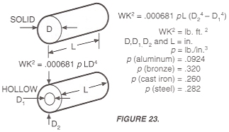
The factor WK2 is the weight (Ibs) of an object multiplied by the square of the radius of gyration (K). The unit measurement of the radius of gyration is expressed in feet.
For solid or hollow cylinders, inertia may be calculated by the equations shown in Figure 23.
The inertia of solid steel shafting per inch of shaft length is given in Table 6. To calculate for hollow shafts, take the difference between the inertia values for the 0.0. and 1.0. as the value per inch. For shafts of materials other than steel, multiply the value for steel by the factors in Table 7.
TABLE 6. INERTIA OF STEEL SHAFTING (PER INCH OF LENGTH)
| Diam. (In.) | WK² (lb ft²) | Diam. (In.) | WK² (lb ft²) |
| 3/4 1 1-1/4 1-1/2 1-3/4 | .00006 .0002 .0005 .001 .002 | 10-1/2 10-3/4 11 11-1/4 11-1/2 | 2.35 2.58 2.83 3.09 3.38 |
| 2 2-1/4 2-1/2 2-3/4 3 | .003 .005 .008 .011 .016 | 11-3/4 12 12-1/4 12-1/2 12-3/4 | 3.68 4.00 4.35 4.72 5.11 |
| 3-1/2 3-3/4 4 4-1/4 4-1/2 | 0.029 0.038 0.049 0.063 0.079 | 13 13-1/4 13-1/2 13-3/4 14 | 5.58 5.96 6.42 6.91 7.42 |
| 5 5-1/2 6 6-1/4 6-1/2 | 0.120 0.177 0.250 0.296 0.345 | 14-1/4 14-1/2 14-3/4 15 16 | 7.97 8.54 9.15 9.75 12.59 |
| 6-3/4 7 7-1/4 7-1/2 7-3/4 | 0.402 0.464 0.535 0.611 0.699 | 17 18 19 20 21 | 16.04 20.16 25.03 30.72 37.35 |
| 8 8-1/4 8-1/2 8-3/4 9 | 0.791 0.895 1.00 1.13 1.27 | 22 23 24 25 26 | 44.99 53.74 63.71 75.02 87.76 |
| 9-1/4 9-1/2 9-3/4 10 10-1/4 | 1.41 1.55 1.75 1.93 2.13 | 27 28 29 30 — | 102.06 118.04 135.83 155.55 — |
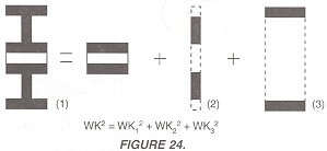
| The inertia of complex, concentric rotating parts is calculated by breaking the part up into simple rotating cylinders, calculating their inertia and summing their values, as shown in Figure 24.FORMULAS TO APPROXI- | TABLE 7.
|
WK² Of Rotating Elements – In practical mechanical systems, all the rotating parts do not operate at the same speed. The WK’ of all moving parts operating at each speed must be reduced to an equivalent WK’ at the motor shaft, so that they can all be added together and treated as a unit, as follows:
| EquivalentWK²=WK² | [ | N | ] | ² |
| Where, | WK² = | Inertia of the moving part Speed of the moving [art (RPM) Speed of the driving motor (RPM) |
When using speed reducers, and the machine inertia is reflected back to the motor shaft, the equivalent inertia is equal to the machine inertia divided by the square of the drive reduction ratio.
| Equivalent WK² = | WK² |
| Where, DR = drive reduction ratio | NM |
WK² Of Linear Motion – Not all driven systems involve rotating motion. The equivalent WK’ of linearly moving parts can also be reduced to the motor shaft speed as follows:
| Equivalent WK² = | W(V)² |
| Where, | W = | Weight of load (lbs) |
| V = | Linear velocity of rack and load or conveyor and load (FPM) | |
| NM = | Speed of the driving motor (RPM) |
This equation can only be used where the linear speed bears a continuous fixed relationship to the motor speed, such as a conveyor.
SPEED REDUCER SELECTION
Continuous operation at rated torque and low speed can damage adjustable-speed drive motors since their self-cooling ability diminishes as speed is reduced.
The motor should always be coupled to the driven machine by a power transmission device that will permit maximum motor RPM at maximum machine speed. The power transmission may be a simple belt-sheave or sprocket-chain arrangement or a compact gear reducer. Where applications require reductions greater than 5:1, the gear reducer may be the most economical choice.
The primary function of a gear reducer is to convert power into a use’
able form. This may mean a change of speed with a corresponding change in torque, a change in output direction or position, or more commonly, a combination of the above.
The gear reducer serves as a torque amplifier, increasing the torque by a factor proportional to the reducer ratio, less an efficiency factor. For example:
A 1 HP, 1750 RPM motor has an output torque of 3 ft-lb. If a 30:1 ratio reducer with 85 percent efficiency is used, the reducer output torque will be 3 x 30 x .85 = 76.5 ft-lb.
SELECTION OF GEAR REDUCERS
A typical application involves selecting a gear reducer that permits the drive motor to operate at base speed when the driven machine is at maximum speed, and also provide adequate torque to drive the machine.
| Problem: | A 1750 RPM motor is selected for a machine which is to operate at a 57.5 RPM maximum speed and requires 70 ft-lb of torque. | ||||||
| The solution involves two steps: | |||||||
| Step A: | Determine the required ratio: | ||||||
| |||||||
| |||||||
| NOTE: | When the drive ratio, thus calculated, is not one of the handbook-listed speed reducer ratios, a chain, belt or additional gears with further reduction for either the input or output side are necessary. | ||||||
| Step B: | Determine motor torque and horsepower: | ||||||
| A 30:1 gear reducer is selected which is capable of supplying 70 ft-lb of output torque. Since the machine torque requirement is known, this value is divided by the reduction ratio and an efficiency factor to arrive at required motor torque (TM). | |||||||
| |||||||
| Since a 1 HP, 1750 RPM base speed motor delivers 3 ft-Ib of torque, it is chosen for this application along with a 30:1 gear reducer with a minimum of 70 ft-Ib output torque. Where the reduction ratio permits the use of chain or belt, the same formulas are used as for reducers. | |||||||
GEAR REDUCER, OVERHUNG LOAD
Overhung load is defined as the dead weight the gear reducer bearings can support, on an output shaft, at a distance equal to the shaft diameter. This distance is measured from the outside end of the bearing housing along the shaft.
When a speed reducer is driven by a belt, chain or gear drive, or when the speed reducer drives a driven unit through a belt, chain or gear drive, an overhung load (side thrust) is produced. The overhung load must not exceed the rating of the gear reducer as listed in the manufacturer’s handbook. The magnitude of the overhung load should always be kept to a minimum. Excessive loads could lead to fatigue failure of either the bearing or shaft. The sprocket or pulley should always be located as close to the gear housing as possible. Also, increasing the sprocket or pulley diameter results in a reduced overhung load. Use the following formula to determine overhung load:
| OHL = | 2 TK D | |
| Where, | OHL = | overhung load (lb) |
| T = | actual shaft torque (in-lb) | |
| D = | diameter of sprocket, sheave, pulley or gear (inches) | |
| K = | 1.0 for chain drives | |
| = | 1.25 for gears or gear-belt drives | |
| = | 1.50 for V belt drives | |
| = | 2.50 for flat-belt drives |
No overhung loads are encountered when the gear reducer is directly coupled to the motor and/or driven machine shaft. However, care must be taken in aligning the shafts to avoid pre-loading bearings by misalignment.
Adjustable Speed Drive Application Information provided by: FINCOR Automation