A1000 600V AC Drive Options 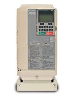
- A1000 600V AC Drive
- Specifications and Features for A1000 600V Drive
- Models & Ratings for A1000 600V Drive
- Network Communications Options for A1000 600V Drive
- Input, Output, and Keypad Options for A1000 600V Drive
1-30 Horsepower
The Drive for the Future . . . Today
Network Communications Options for A1000 600V Drive
These communication cards provide the interface between industrial networks and Yaskawa AC drives. These options may be factory installed or field installed.
Compare this drive’s Network Communications Options to other Yaskawa AC drives.
| Network Communications Option | Option Card # & Mounting Location | Installation Manual | Technical Manual & Latest Support File |
| DeviceNet™ With ADR – Each DeviceNet network supports up to 63 drives. Controllers are available from many PLC and/or PC suppliers. The DeviceNet network communications option board is designed to comply with all pertinent aspects of the ODVA (Open DeviceNet Vendor Association) specification and AC drive profile. All parameters, diagnostics, and operational commands are accessible via DeviceNet. Automatic Device Replacement (ADR) is supported in this DeviceNet option, including the functions of Auto Baud Rate sensing and Faulted Node Recovery (using Group 4 messaging). The DeviceNet satellite board mounts integrally in the drive and provides a DeviceNet standard open tap connector. Electronic Data Sheets (EDS) may be downloaded to assist with network configuration and drive setup. | SI-N3 CN5-A | TOBPC73060043 | SIEPC73060043 EDS File |
| EtherNet/IP – This option complies with the EtherNet/IP protocol specification. This allows for communication over 10/100 Mbps Ethernet networks. This option has the ability to configure the IP Address from a user specified IP address, from a DHCP host, or from a BootP host. All parameters, diagnostics and operational commands are accessible via EtherNet/IP. Auto-tuning the motor is also possible through this option using the DriveWizard PC program. | SI-EN3 CN5-A | TOEPYEACOM04 | SIEPYEACOM04 EDS File |
| MECHATROLINK-II – This option is designed for connecting a drive to a field network using the MECHATROLINK protocol. The MECHATROLINK-II option allows the user to operate the drive, monitor the status, and change parameters from a MECHATROLINK master device at a communication speed up to 10Mbps. | SI-T3 CN5-A | TOBPC73060050 | SIEPC73060050 |
| Modbus TCP/IP – This option complies with the Modbus TCP/IP protocol specification. This allows for Modbus communication over 10/100 Mbps Ethernet networks. This option has the ability to configure the IP Address from a user specified IP address, from a DHCP host, or from a BootP host. All parameters, diagnostics and operational commands are accessible via Modbus TCP/IP. Auto-tuning the motor is also possible through this option using the DriveWizard PC program. This option supports up to 10 simultaneous PLC/PC connections. | SI-EM3 CN5-A | TOEPYEACOM05 | SIEPYEACOM05 |
| Modbus RTU RS-232 – Complies with a subset of Modicon’s Modbus RTU specification, referred to as Memobus by Yaskawa. All parameters, diagnostics and operational commands are accessible. The RS-232 Modbus RTU network allows for one drive to be accessed by the controller. | Embedded CN2-2 | N/A | SIEPC71061631 |
| Modbus RTU RS-485 – Complies with a subset of Modicon’s Modbus RTU specification, referred to as Memobus by Yaskawa. All parameters, diagnostics and operational commands are accessible. Each RS-485 Modbus RTU network supports up to 32 drives. | Embedded Terminal Strip | N/A | SIEPC71061631 |
| PROFIBUS-DP – This option complies with the Profibus- DP protocol specification. All parameters, diagnostics and operational commands are accessible via Profibus. The option board provides a 9-pin (F) type D-Sub connector for easily connecting to a standard Profibus style, shielded twisted-pair cable. Each Profibus network supports up to 99 drives. This option supports all of the Profibus data rates from 9.6 Kbps to 12 Mbps. Up to 32 bytes of input data and 32 bytes of output data are provided per message transaction. Sync and Freeze modes are supported for groups. Profibus DP-V1 support (cyclic and acyclic data exchange). Configurable PPO read and write parameters. The option is configured using parameters within the drive, which allows for easy configuration eliminating the use of hardware switches. Status LEDs are viewable through the front cover, and a monitor has been added to allow for improved diagnostics. | SI-P3 CN5-A | TOBPC73060042 | SIEPC73060042 GSD File |
Download communications software files from this website through the Downloads section/Network Support Files.
Copyright © 2010 Yaskawa Electric America, Inc. All Rights Reserved.
Input, Output, and Keypad Options for A1000 600V Drive
This array of option cards can extend the flexibility and adaptability of Yaskawa AC drives. These options may be factory installed or field installed.
Compare this drive’s Input Output Options to other Yaskawa AC Drives.
| Analog Inputs | Option Card # & Mounting Location | Installation Manual |
| (13 Bit + Sign) – Provides interface of 3 high resolution analog inputs to the drive. Signal levels (individually selectable): 0 to +/- 10 VDC (20kOhm) or 4 to 20mA (500 ohm). Input resolution: Voltage (1/8192), Current (1/6654). | AI-A3 CN5-A | TOBPC73060038 |
| Digital Inputs | Option Card # & Mounting Location | Installation Manual |
| (8, 12, or 16 Bit) – Provides interface of a 16 bit digital input (binary or BCD) to the drive. Signal type is selectable by parameter setting for: Binary 16 bit, 4 digit BCD Binary 12 bit, 3 digit BCD Binary 8 bit, 2 digit BCD | DI-A3 CN5-A | TOBPC73060039 |
| Analog Outputs | Option Card # & Mounting Location | Installation Manual |
| (11 Bit + Sign) – Provides 2 signals for remote metering of any two of the drive’s “U1” monitors. Additive to the two standard analog outputs. Signal level: 0 to +/- 10 VDC (20kOhm). | AO-A3 CN5-A, B, or C | TOBPC73060040 |
| Digital Outputs | Option Card # & Mounting Location | Installation Manual |
| (8 Channels) – Provides 8 additional digital outputs for use in monitoring the status outputs of the drive. Signal levels: 2 channels of Form A, 250 VAC, 30 VDC, 1 A and 6 channels of PHC, 48 VDC, 50 mADC, Shared Common. | DO-A3 CN5-A | TOBPC73060041 |
| Encoder (PG) Feedback | Option Card # & Mounting Location | Installation Manual |
| Single Encoder – Line Driver – Provides velocity and direction feedback from an encoder. Primarily used for motor speed feedback in closed loop flux vector control. A 5 VDC buffered output is also included. Signal levels: 5 or 12 VDC differential line driver with compliments, maximum input frequency of 300 kHz, phases A and B (Z required with some custom software). | PG-X3 CN5-C or B | TOBPC73060037 |
| Single Encoder – Open Collector – This option provides velocity and direction feedback from an encoder. This is primarily used for motor speed feedback in closed loop flux vector control. A 24DC buffered output (open collector) is also included. 32 kHz maximum input frequency. | PG-B3 CN5-C or B | TOBPC73060036 |
| Keypad Options | Option Card # & Mounting Location | Installation Guide & Technical Manual |
| The LED Operator allows the drive to be operated from a remote location up to 3-meters.JVOP-182 Kit Contents: Qty Description 1 LED Operator 1 Installation Manual (TOBPC73060035)Note: This option requires Installation Set A (EZZ020642A) for panel or door mounting and Remote Operator Cable (UWR0051 or UWR0052), each sold separately. | JVOP-182 RJ-45 Keypad Port | TOBPC73060035 |
| USB Copy Unit (Y-Stick) | Model Number & Mounting Location | Installation Guide & Technical Manual |
Qty Description 1 USB Copy Unit (Y-Stick) 1 1 ft USB Cable to connect PC to Y-Stick 1 3 ft Cable with RJ-45 connector on both ends to connect Y-Stick to drive 1 Technical Manual (TOBPC73060025)Driver: SP1824_001 Note: This driver is required to be installed on the PC before the Y-stick can be used. | JVOP-181 RJ-45 Keypad Port | IG.V1000.01 TOBPC73060025 |
| CopyUnitManager PC Software CopyUnitManager is a PC software program that works along with the Y-Stick Copy Unit (JVOP-181) that allows the user to transfer and save parameter files from the Y-Stick to a PC and vice versa. The CopyUnitManager software can be used to save parameter files for a variety of drive sizes and parameter configurations. Simply configure the drive parameters, transfer them to the Y-Stick Copy Unit, then save them to your PC for backup or for quickly downloading multiple drives.> Download Software (5.9MB)System Requirements
| ||
| UL Rated Remote Operator Kit This option is used to extend the existing Digital Operator to the wall of a separately priced, oversized UL Type 1, 3R, 4, 4X, or 12 enclosure (IPX6 environment). Price includes a faceplate bezel with digital operator brackets and membrane to cover the operator cutout in the enclosure door, a 3-foot cable, a 10-foot cable, and a 1:1 template for cutting the necessary cutouts in the enclosure. Keypad can be removed after kit installation. Designed for use with the LCD Operator JVOP-180 or the LED Operator JVOP-182 sold separately. | UUX000526 (Blank Membrane) Connects to RJ45 port and mounts to enclosure door. | TOEPYEAOPT02 |
| UUX000527 (Yaskawa Logo Membrane) Connects to RJ45 port and mounts to enclosure door. | ||
Copyright © 2010 Yaskawa Electric America, Inc. All Rights Reserved.