 Guide to Harmonics
with AC Variable Frequency Drives
Contents
- Introduction
- Basics of the harmonics phenomena
- Harmonic distortion sources and effects
- Harmonic distortion calculation by using DriveSize software
- Circuit diagram for the calculation example
- Input data for motor load
- Motor selection
- Inverter selection
- Inverter supply unit data
- Network and Transformer data input
- Calculated harmonic current and voltage
- Calculated harmonic currents in graphical form
- Part of the printed report
- Standards for harmonic limits
- EN61800-3 (IEC1800-3) Adjustable speed electrical power drive systems
- IEC1000-2-2, Electromagnetic compatibility (EMC)
- IEC1000-2-4, Electromagnetic compatibility (EMC)
- IEC1000-3-2, Electromagnetic compatibility (EMC)
- IEC1000-3-4, Electromagnetic compatibility (EMC)
- IEEE519, IEEE Recommended practices and requirements for harmonic control in electrical power systems
- Evaluating harmonics
- How to reduce harmonics by structural modifications in the AC drive system
- Factors in the AC drive having an effect on harmonics
- Table: List of the different factors and their effects
- Using 6-pulse diode rectifier
- Using 12-pulse or 24-pulse diode rectifier
- Using phase controlled thyristor rectifier
- Using IGBT bridge
- Using larger DC or AC inductor
- Other methods for harmonics reduction
- Tuned single arm passive filter
- Tuned multiple arm passive filter
- External active filter
- Summary of harmonics attenuation
- 6-pulse rectifier without inductor
- 6-pulse rectifier with inductor
- 12-pulse rectifier with polygon transformer
- 12-pulse with double wound transformer
- 24-pulse rectifier
- Active IGBT rectifier
- Definitions
Harmonic distortion sources and effects
Common non-linear loads include motor starters, variable speed drives, computers and other electronic devices, electronic lighting, welding supplies and uninterrupted power supplies.
The effects of harmonics can be overheating of transformers, cables, motors, generators and capacitors connected to the same power supply with the devices generating the harmonics. Electronic displays and lighting may flicker, circuit breakers can trip, computers may fail and metering can give false readings.
If the cause of the above mentioned symptoms is not known, then there is cause to investigate the harmonic distortion of the electricity distribution at the plant. The effects are likely to show up in the customer’s plant before they show on the utility system. This Technical Guide has been published to help customers to understand the possible harmonic problems and make sure the harmonic distortion levels are not excessive.
Harmonic distortion calculation by using DriveSize software
The harmonic currents cause a distortion of the line voltage. In principle the voltage harmonics can be calculated at any point of the network if the harmonic currents and the corresponding source impedance are known. The circuit diagrams in Figure 4.1. show the network supplying the converter and the other essential parts of the installation. ABB DriveSize software is used for the calculation example.
Circuit diagram for the calculation example

Figure 4.1. Network supplying a frequency converter in the middle and its equivalent diagram on the right. The data for this example is on the left.
Input data for motor load

Figure 4.2. The most important motor load data for harmonics calculation is the base power in kW.
Motor selection

Figure 4. 3. The software makes the motor selection for the defined load. If required there is an option to select a different motor than that selected by the DriveSize.
Inverter selection

Figure 4.4. The inverter selection is based on the previous motor selection and here also the user has an option to select the inverter manually.
Inverter supply unit data

Figure 4.5. The supply unit data is defined by DriveSize according to the inverter type selected.
Network and Transformer data input

Figure 4.6. The network and transformer data input is given here. For standard ABB transformers the data is shown automatically.
Calculated harmonic current and voltage

Figure 4.7. The harmonics are calculated by making discrete Fourier transformation to the simulated phase current of the incoming unit. Different kinds of circuit models are used, one for SingleDrive with AC inductors and one for diode and thyristor supply with DC inductors. There are also models for 6, 12 and 24 pulse connections.
Calculated harmonic currents in graphical form

Figure 4.8. The results of calculations can be shown in table form as above or as a graph.
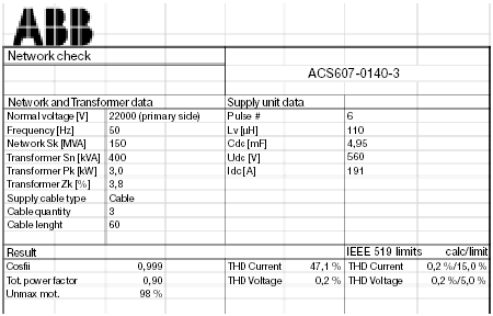
Part of the printed report

Figure 4.9. The input data and calculated results can be printed out as a report, which is partly shown here.


 Guide to Harmonics