Ground Faults: Typical Variable Speed Drive Faults and How to Troubleshoot Them
Variable speed drives are equipped with some degree of protection against ground faults generated on the load (output) side of the drive. This is intended to protect the drive in the event of a fault in the motor leads or the motor itself. Here we examine the causes and effects of these faults on drives, and ways of resolving them.
Variable speed drive (VSD) ground faults are intended to trip the drive before its output power section is damaged. They are typically displayed as “GF” or an analogous code on the drive’s HMI. These faults may also be termed “earth leakage” in some drive manuals. When they occur, they usually indicate problems with the connected cabling or motor, and need to be addressed promptly. Let’s explore some basic causes and corrective measures.
The most common causes of drive ground faults are motor cables shorted to ground, or motor windings shorted to ground. As we have referenced in past articles, the characteristics of the synthesized AC output voltage and current from a pulse width modulated (PWM) variable frequency drive (VFD) can place additional stresses on cables, motor leads and windings. Particularly on older motors and cables, these stresses can lead to premature failure of the insulation systems used to protect them. These failures must be of significant magnitude for the drive to sense them and trigger a fault; most drives will not trip unless a ground fault current of about 50% of rated output current is detected. Clearly, at that point a significant failure has already occurred and must be dealt with before again operating the drive. We’ll deal with the concerns surrounding this issue later; for now, let’s discuss the causes of the faults, their effects, and how to diagnose them in more detail.
Ground faults in cables can be caused by insulation breakdown, leading to a line conductor shorting to ground. The capacitive reactances of the drive, cable and motor are rarely identical, and this means that, when supplied by a VFD, voltage levels in the cables can build up through the process of resonance. In severe cases, this voltage can exceed the corona inception voltage of the cable, leading to an electric field (corona) building up on the surface of the cable. This field can ionize the surrounding air, creating by-products which can break down some types of cable insulation. Eventually the insulation breaks down enough that it shorts to ground, causing the fault. Even if this doesn’t happen, the high-frequency, steep wave front pulses sent by the drive can easily overcome the capacitive reactance of the cable, leading to leakage and capacitive coupling to adjacent cables and conduits. In some smaller drives this leakage current can even be sufficient to cause overcurrent trips. And in any case, this leakage current places additional load on the drive and cables.
Similarly, ground faults in motor windings occur when winding insulation degrades enough that the windings short to the motor ground. As with the cables, this can occur due to voltage increases caused by resonance in the drive-to-cable-to-motor connections. Of course, motors also generate heat, and that heat may be increased due to stray circulating currents induced by the high-frequency pulses generated by the VFD. This in turn increases the stress on the motor winding insulation.
It is also possible, though less likely, that internal drive components can fail and cause a ground fault trip. The drive’s DC current transformers might be the culprits. Once they are defective they will fail to properly sense DC current output and can result in a ground fault trip.
It should also be noted that some DC drives, such as Siemens Sinamics 6RA80 series, can be set up to conduct a thyristor self-test to detect internal faults in the power section, as well as having standard ground fault protection for the armature leads and motor.
So how to go about locating the source of the ground fault and dealing with it? One of the easiest things to do is to power down the drive, disconnect the motor leads, and restart the drive. (Note: before shutting down, you will need to disable the drive’s Phase Loss protection. The means to do this varies from drive to drive, and will be found in the user manual.) If the drive still trips on ground fault, then the issue is internal to the drive. If not, you can direct your attention to the motor cables and/or motor. Disconnect the cables from the motor and drive, and test the insulation on each separately until a fault is found. Typically the resolution will either be to replace the damaged section of cable, or rewind or replace the motor. Note that while it is possible in most drives to disable ground fault protection, under no circumstances should the drive be allowed to continue to operate before the problem is fixed, as even more costly, catastrophic damage to property or personnel can occur.
If the VSD does trip on ground fault even after motor leads have been disconnected, then the problem is likely internal to the drive. If the DC CT’s are suspected to be failing, as is sometimes the case in these fault conditions, they should be replaced. You will likely find that it is easier and less costly to replace all, or sometimes even the entire drive, rather than trying to identify and replace only the faulty one. In order to correctly diagnose a DC CT problem an oscilloscope and considerable technical knowledge will be needed.
Finally, there are some general, but important, considerations regarding ground faults in drive applications which should be mentioned. First, the ground fault protection provided in drives is intended for protecting against faults in the output only; input ground fault protection relies on external ground fault protection relays which must be capable of sensing DC as well as AC faults in order to protect the drive input section. In cases where the drive is supplied by a solidly grounded system (“TN” per IEC 60364), the upstream overcurrent protective device will usually protect the drive in the case of a phase-to-ground fault, although the magnitude of the ground fault current may be large. This is one reason why high speed fuses are recommended for drive protection – they limit the peak let-thru current to levels below what the drive power section can withstand without damage.
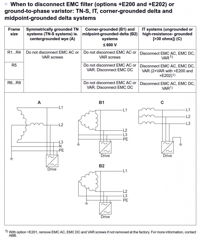
On the other hand, many facilities are supplied by resistance-grounded systems. These systems limit fault current to levels which can reduce or even eliminate arc flash concerns, and are also sometimes specified to reduce the chance of a power shutdown in case of a fault. Resistance grounded systems present special challenges for drive installations. For one thing, if the drive is equipped with an EMI filter it must be disconnected whether the system grounding is low-resistance, high resistance, or ungrounded (IT). This is because the filter is connected to the drive ground to divert noise and/or leakage current away from the supply line; if a ground fault occurs elsewhere in the system, a ground loop can result and additional fault current can flow through the filter, destroying it and potentially damaging the drive. Typically, these systems are also protected by external ground fault relays, but they are largely for personnel protection and should not be solely relied upon to protect sensitive drive components.
Corner-grounded or center-tapped ground systems also present challenges to the drive, insofar as the line-neutral voltage rises in the event of a fault. The EMI filters are not intended to handle the higher voltages seen when that occurs. And some manufacturers prohibit the use of higher voltage (690V) drives on corner-grounded or center-tapped ground systems entirely, because even disconnecting the filters will not protect the drive sufficiently. All said, it is important to fully understand both supply and load conditions when confronted with these types of drive or system faults.
ABB sums all these concerns with respect to their ACS880 drive series in Fig. 1:
Ground faults can sometimes seem mysterious, so it is critical to use the capabilities of the drive to help diagnose problems and pursue a step-by-step evaluation to correct them. If you have an experience you’d like to share with our readers, leave a Comment below. And as always, if you need assistance, please email us or call us at 866.492.9888.
Thanks for reading, and we’ll catch you next time.

Regards,
Jay Baima
Joliet Technologies
Leave A Comment
You must be logged in to post a comment.