Today we look at overvoltage faults, as we continue with some of the more common faults experienced by variable speed drives, their causes, and some ways to resolve them.
Variable Speed Drives (VSDs, a.k.a. Adjustable Speed Drives (ASDs) or, for AC motor control, Variable Frequency Drives (VFDs)) are equipped with a number of monitoring and control features intended to protect the drive and its connected equipment from damage. Errors, Warnings, and Faults are logged in response to abnormal operating conditions and displayed on the drive’s HMI and/or sent to monitoring software in connected PCs or automation control systems. The drive’s response to the abnormal condition depends on the condition’s severity, and the potential it has to inflict damage. The faults we are discussing typically cause drive shutdown, and require that the fault be corrected and the drive reset or rebooted before it can operate normally.
One relatively common fault is over-voltage, often shown as “OV” or “OU” or similar, and often with an accompanying description of “DC Link Overvoltage”. Fundamentally, this fault is in response to the drive’s internal DC bus seeing a voltage higher than the limit specified in the drive settings. Most of the time, this fault occurs when the drive is attempting to quickly decelerate a high-inertia load; the motor is then overhauled by the load and becomes, in effect, a generator, pushing current back into the drive and recharging the DC capacitors before its DC bus voltage has had time to bleed off. The generated voltage then adds to the existing bus voltage, causing the overvoltage. Many drives have user-selectable settings intended to reduce the likelihood of this fault under conditions of rapid deceleration or in response to quick changes in load. For example, ABB’s ACS880 series drive uses an algorithm called Overvoltage Control, which attempts to reduce the generating torque to keep the DC bus voltage below the control limit. (See Fig. 1.) In the case of the ACS880, the DC bus voltage control limit is between ~775-800VDC for an input (supply) voltage of 440-480VAC.
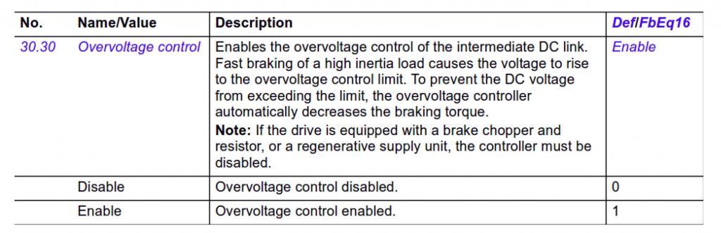
Courtesy of ABB, Inc.
Yaskawa’s GA800 series uses an analogous approach via parameter L3-04, called “Stall Prevention During Decel,” which monitors bus voltage closely and adjusts drive output to maintain it below upper limits. (See Fig. 2.) In the case of a 400V-class GA800, that DC bus upper limit is ~820VDC.
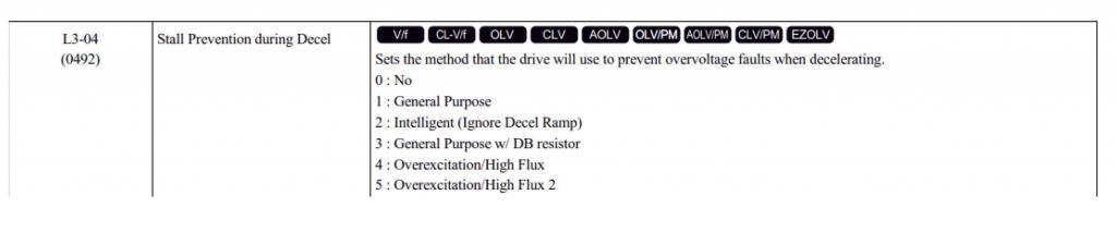
Courtesy of Yaskawa America, Inc.
Acceleration and deceleration parameters can also be manually adjusted to fine tune the ramping profiles, adding time to each if needed to “soften” starting and stopping and prevent overvoltage. See each drive’s operating manual for specific instructions.
The above approaches are intended to address one of the most common causes of overvoltage faults, overhauling loads. We find the potential for this occurs often in higher inertia centrifugal loads, such as large diameter fan applications, when required to decelerate quickly. Even though these are typical variable torque loads, the mass of the larger impellers and the pressure changes in the pipe or duct during a rapid deceleration can result in an overhauling condition.
There are other means for dealing with overvoltage faults caused by overhauling loads in addition to these software-based approaches. Drives can include dynamic braking circuitry, either internally or externally. A braking circuit is also sometimes referred to as brake chopper, and is essentially a switch which closes in response to a rapid rise in DC bus voltage above rated value. The excess voltage is then dumped as heat across a large resistance. (See Fig. 3.) In very small drives, this circuitry is internal, but in mid-sized and larger drives takes the form of a separate braking module and resistor cabinet. The braking circuit responds very rapidly to the back-fed voltage to protect the DC bus. However, the high heat generated means a loss of overall system efficiency. Even though the braking duty cycle is typically low, proper sizing of the resistors is critical to ensuring the circuitry lasts and losses are kept as low as practical. For more information on dynamic braking, please read one of our previous blogs here.
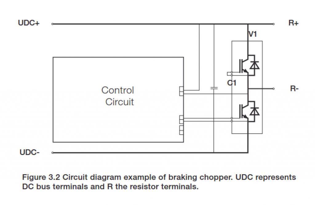
Courtesy of ABB, Inc.
Short circuits and ground faults in the motor wiring or motor, or in the drive itself, can also cause overvoltage faults. Check the condition of the load wiring and the motor to ensure they are not the cause of the problem. If they are free from defect, test the VSD. One way to do this is to power down the drive (making sure any residual DC voltage bleeds off before accessing the terminals), disconnect the motor leads from the drive, turn the drive back on, and ramp the drive to full speed. If the drive faults out it must be repaired or replaced. Another option would be to swap the faulting VSD with a unit known to be working properly; if the working unit doesn’t fault, it is likely the original drive needs to be repaired or replaced.
If the mechanical and electrical characteristics of the application haven’t changed and you have been seeing an increase in overvoltage faults, it is also a good idea to inspect the mechanical load linkages (couplings, pulleys, gearboxes, etc.) to make sure they are not binding or slipping and causing voltage spikes due to rapid load changes.
There are other causes of overvoltage faults as well. For example, the incoming power can surge due to environmental or power distribution issues (Utility hardware failures, upstream load transfers, substation maintenance, and a host of other possibilities). While controlling the sources of these anomalies is often beyond the facility’s capability, VSDs can be protected from these surges to varying degrees through the use of DC link chokes, smoothing capacitors, line-side AC reactors, or surge protective devices (SPDs) – for lightning-induced or switching transients. DC link chokes, installed internally on the drive’s positive (and sometimes negative) DC bus(es), provide some limited protection but saturate quickly and are intended primarily to act as filters by reducing harmonic distortion on the incoming line. Because they are installed downstream of the drive’s rectifier bridge, they cannot protect the front end of the drive, including the rectifiers, from surges. Most drives also utilize smoothing capacitors on the DC bus to reduce AC ripple remaining on the DC rail after rectification. They can have a significant impact on DC bus voltage – a full-wave rectification system with an incoming 480VAC supply can impress upwards of 30 – 40VAC ripple onto the DC bus voltage without smoothing. Sizing of these capacitors is done by the manufacturer and is normally not accessible to the end user. AC reactors are very effective at protecting the drive’s rectification stage by absorbing the lion’s share of the surge before they saturate. However, they need to be sized correctly, since they do introduce some voltage drop at the line-side drive terminals. And SPDs are high-energy shunting devices intended only to protect against rapid voltage spikes (with 8-10µs rise times). They do not protect against longer duration or sustained increases in supply voltage.
In some cases, VSDs are subjected to consistently higher incoming voltage levels, for example when a facility is located near a Utility substation and consumer use downstream is light. Drives are typically rated for +10%/-15% of nominal voltage; supplies outside of this range can cause problems. We have seen DC bus voltages in excess of 840VDC when incoming supply was about 505VAC, so even though the supply voltage was technically within spec there was very little overhead when using default factory settings. Many drives allow incoming supply voltage settings to be manually adjusted within specification range; lowering the incoming voltage parameter toward the low end of the range (i.e. -10% of nominal) can sometimes resolve the DC bus overvoltage, but this affects many of the protective functions of the drive and so should be done only under carefully evaluated conditions. Care must also be taken when doing this to ensure that the resulting lower output voltage is still sufficient to handle the load. If the Utility is unable or unwilling to do anything about the higher supply voltage, some site transformers have taps which can be changed to lower the incoming voltage. In more extreme cases, buck-boost transformers can be used where cost-effective to do so.
Of course, some VSDs see overhauling loads as a normal part of their operation, and if properly sized don’t usually see overvoltage faults due to overhauling loads. For example, lifting applications usually have to raise and lower loads in a controlled fashion, despite load and gravity. This means that for a part of their operation torque needs to be controlled in a direction opposite to motor rotation. Variable speed drives built to control these operations accomplish this through regeneration; i.e. they can control power flow both to and from the motor they control, passing any motor-generated power back to the supply line.
Have you had experience dealing with drive overvoltage faults? If so, how did you resolve them? Please let our readers know in the Comments section. And if you are having issues with VSD faults of any type, please don’t hesitate to contact us by phone (866.492.9888), fax (815.725.9393), or email (info@joliettech.com). You can also fire off a question to us on our site via our Ask a Professional page. There is also a great deal more information at joliettech.com. We’re looking forward to your visit!
Please stay tuned next time when we review causes of and solutions to another VSD fault condition. Thanks for reading!

Regards,
Jay Baima
Joliet Technologies
Leave A Comment
You must be logged in to post a comment.