Today we examine the Output Phase Loss fault, as we continue with common Variable Speed Drive faults, their causes, and some ways to resolve them.
As noted in our previous articles, Variable Speed Drives (VSDs, a.k.a. Adjustable Speed Drives (ASDs) or, for AC motor control, Variable Frequency Drives (VFDs)) are equipped with a number of monitoring and control features, including extensive monitoring of power output to the load. One critical function monitored is the health of each phase of the VSD’s output; when a fault occurs there, it is termed an Output Phase Loss. Let’s examine what triggers this fault, and how to address it. Output Phase Loss is typically indicated on the drive’s HMI by some alpha or numeric designation, which varies depending on the drive. For purposes of this discussion, we’ll note it is indicated by “LF” (in the case of the Yaskawa GA800) (see Fig. 1) or a numerical code (on the ABB ACS880, “3381”). This condition can result from a number of problems related to the output cabling, the connected motor, or the VSD’s output (inverter) section. One of the most common causes is a break in the connection to the motor, either in the motor leads (cables from drive to motor) or in the motor itself. Breaks can be caused inadvertently, such as when a short circuit occurs in one or more of the motor leads; or deliberately, for instance when a contactor is located between the drive output and the motor, but fails or is not properly interlocked with drive operation. Both conditions can severely damage the drive so the drive faults and shuts down, usually before any damage to the drive can occur. As is typically the case with faults, the cause must be corrected before the drive can be reset to resume operation. Let’s examine some of these causes in more detail; this will give us insight into the proper corrective measures.
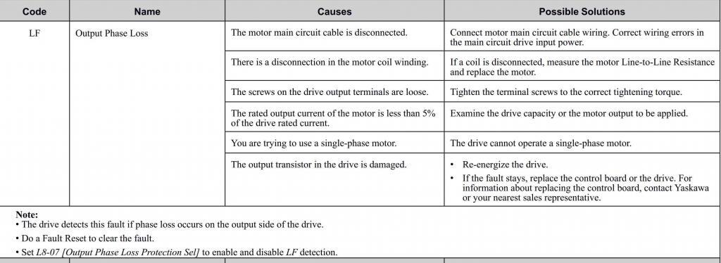
(Courtesy Yaskawa America, Inc.)
Motor short circuits generally occur as a result of winding insulation failure. As motors age, their insulation systems gradually break down. This breakdown can be the result of several factors, including internal heating, vibration, voltage imbalance between phases, loose (high resistance) connections, stray circulating currents, etc. In addition, where AC drive systems are employed, the motor insulation can be subjected to additional voltage stress. This is the result of the rapid rise times of the voltage pulses the typical Pulse-Width Modulation (PWM) VFD outputs to the motor interacting with the impedances of the motor and connecting cabling (see Fig. 2).
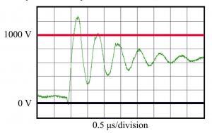
(Courtesy ABB, Inc.)
It is not uncommon to see voltages at the motor terminals of between two and four times line voltage. Newer motors are built with insulation systems designed to handle these higher voltage levels, but many older motors are not. Eager to take advantage of the energy savings opportunities a VFD can provide, or faced with the need for adjustable speed control as processes change, many users opt for drives without carefully evaluating the condition of their existing motors. Sometimes, motors with insulation systems compromised by years of use are retrofitted with VFD control, only to cause the motors to fail relatively quickly. If the users are paying close attention, and performing proper preventive maintenance on these motors, there are often early warning signs of impending insulation failure. One such sign may be a drive overcurrent fault, as we discussed in a previous article.
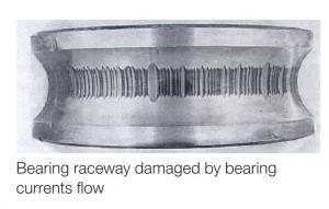
VFDs can also raise motor internal temperatures by causing stray circulating currents to flow between stator and rotor, and between the shaft and bearings. These currents form due to internal capacitances which develop because motors are not perfectly magnetically symmetrical. Variations in materials and methods during fabrication can result in slightly eccentric rotors; rotor and stator slots cause flux imbalances which vary with motor speed; the lay of windings is never perfectly controlled; etc. Shaft voltages can result in any motor, VFD-driven or not, due to this dissymmetry. Low level voltages are often not a concern. However, higher shaft voltages can result when a PWM VFD is used, because the motor internal capacitances easily pass the high frequency current pulses generated by the drive. Higher shaft voltages result in increased circulating currents and increased internal temperatures. Beyond that, once the shaft voltages become high enough, they can break down the dielectric of the bearing lubricating grease and cause pitting and fluting of the bearings and races, referred to as electrical discharge machining (EDM) (see Fig. 3). If such damaged bearings are not replaced, this places additional stress on the motor.
The most common other cause of motor short circuit results from motor terminations working loose. Space inside motor termination boxes is limited and motor leads are often not long. In older motors, wiring labels can become unreadable or fall off. It is incumbent upon qualified personnel to ensure that the terminations are made and insulated properly, and then periodically inspected to ensure integrity.
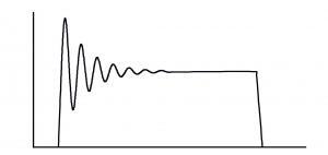
Failures in cables from the VSD to the motor can also cause Output Phase Loss faults. Line-to-line and line-to-ground faults are the most obvious, and they can be caused by a number of environmental, mechanical or electrical factors. One of these electrical factors, corona discharge, is directly influenced by the use of a VFD. Corona is essentially the ionization of the air surrounding an electrical field, and the consequential breakdown of the adjacent air. If the cable insulation isn’t sufficient for the voltage impressed on the conductor, the electric field can “bleed through” at weak points and ionize the surrounding air. This creates ozone at the site, which in turn causes breakdown of rubber compounds in the insulation. If moisture is present, it can also produce nitric acid, which further breaks down compounds in the insulation. Over time, this leads to premature insulation failure. PWM VFDs contribute to this because, as mentioned above, they generate rapid rise-time pulses which rise from 10% to 90% of peak bus voltage in about 0.1µs. These pulses thus present very steep, high frequency wave fronts which traverse the length of the cables and “crash” headlong into the motor terminals, which present a very different impedance than the cables. The pulses are then partially reflected back onto the cables, where under certain conditions they add to the voltage being sent from the VFD. If the cables are long (say, 50m or more), and the differences between the cable and motor impedances are sufficient, the pulses can add significantly, resulting in high voltages across the cable and at the motor terminals (see Fig. 4). These high voltages render components more susceptible to corona discharge, and thus premature failure.
Two other, less common, conditions can also lead to Output Phase Loss. First, if the motor full load amperage is very low compared to the output capacity of the drive, the drive may not be able to lower its output sufficiently for any extended period, and fault out on phase loss. Second, the drive itself may have failed; a shorted or open output transistor (IGBT) or controlled board failure might be the culprit.
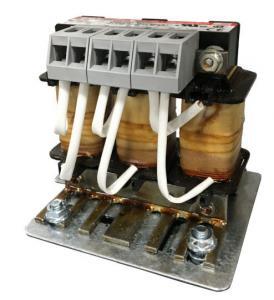
So, how do you ideally prevent, or worst case correct, these fault conditions? With respect to motor faults, once the motor insulation begins to fail it is only a matter of time before you need to face expensive rewinding or motor replacement. So ideally you want to stop motor insulation breakdown before it occurs. First, to reduce excessive voltages at the motor terminals, look at cable length, specifications, and installation methods. If the cables are in excess of 50m per phase (from drive output terminals to motor terminals), it is likely that using a drive output filter would be of help. There are a handful of different filter types available, but the two types most commonly used are dV/dt filters (Fig. 5) and sine wave filters. dV/dt filters are reactors; their inductance is intended to lengthen the rise time of the drive output pulses, slowing them down and allowing the motor capacitance to charge in sync with the pulses, thereby reducing reflected waves. Sine wave filters are more complex low-pass LC filters, designed to produce a clean sine wave output. They are significantly more expensive, but they are typically not needed except in the case of extremely long cable lengths (on the order of 500m or more).
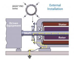
To reduce the likelihood of bearing pitting, motor manufacturers will sometimes provide bearing isolation, typically on the ODE (opposite the drive end) but optionally on both bearings. Isolating the ODE bearing is sometimes sufficient to interrupt current flow through the bearings and reduce EDM. However, under the higher electrical stresses induced by higher voltages or larger motor frame size, shaft grounding rings such as those manufactured by Electro Static Technology (Fig. 6) can also be installed to electrically bond the shaft to the frame. Use of both bearing isolation and shaft grounding will ensure protection of bearings, as well as eliminate current paths through directly coupled shafts of driven equipment.
Also, make sure the cable used is adequate for drive applications. While installation methods play a more important role, materials of construction and resulting cable impedance are important to look at as well. Thicker insulation and the use of properly constructed multi-conductor VFD cabling can reduce the voltage-adding effect of capacitive coupling and the damage from corona discharge. Cables in environments subject to moisture should be rated as such; for example, crossed-linked polyethylene (XLPE) is intended for moist environments and if sufficiently thick can withstand corona discharge more effectively.
It is also critical to ensure that proper installation methods are adhered to. In cases where VFD-rated cable is not used, ensure conductors are routed in steel conduit and properly ground to a common system ground. If not properly grounded, circulating ground loops can form and cause failure of connected equipment, as well as EMI and RF noise. Where the drive would be located distant from the motor, evaluate whether a closer location could work. Motor lead length recommendations vary by manufacturer; consult their online sites or their respective VSD IOM manuals for specific information. If longer motor leads are unavoidable, consider the use of a drive output filter, mentioned above.
Have you had to deal with the frustration of an Output Phase Loss fault? If so, please share your experiences by leaving a comment. And if your struggle continues, please allow us to bring our years of experience and know-how to bear on your issue. Contact us today by email or phone (866.492.9888).
Please drop by next time when we examine another fault situation and its resolution. Thanks for your time!

Regards,
Jay Baima
Joliet Technologies
Leave A Comment
You must be logged in to post a comment.