In some motor applications the inertia profile can be such that once power is removed the motor effectively becomes a generator, feeding power back into the control system at a gradually decreasing magnitude until motor speed decreases. For adjustable speed drives (ASDs) this presents a primary problem – the risk of DC bus over-voltage as the capacitors charge in response to the “reverse” power flow. Modern ASDs resolve this problem differently depending on the configuration of their power components (typically uncontrolled or controlled rectifier arrays referred to as “bridges”). Regenerative drives (often referred to as 4-quad), made for handling reverse-torque applications such as elevators, utilize anti-parallel bridges – one set conducts from drive to motor, and the other from motor to drive – to dump the generated power back into the supply line. Non-regenerative ASDs (sometimes referred to as single-quad) do not have this capability and so must use other means of dissipating the back-fed power, namely a brake chopper circuit. So as to avoid confusion with injection braking technology, let’s examine the brake chopper in more detail. Much of what follows is taken from ABB’s “Technical Guide no. 8: Electrical Braking”, which can be found in the Download Center at abb.com.
A brake chopper is a switching circuit which closes when a pre-set DC bus voltage limit is reached and diverts power through what is termed a discharge resistor, which converts the energy to heat. It is used to supplement the over-voltage control inherent in most modern ASDs, which in most cases is not adequate to handle a significant amount of power generated by the load. For example, the time required for a given power to be dissipated in a drive to prevent exceeding the DC bus capacitors’ withstand rating is calculated by the formula:
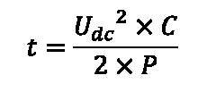
Where:
Udc = DC bus voltage (above rated)
C = capacitance (in farads)
P = power (in watts)
In the case of a 460V drive, rated DC bus voltage is 460Vac x 1.35 = 621Vdc, and capacitance is very low, on the order of 5 millifarad. A typical withstand value for the capacitors is 1.3x the rated value, in this case 807Vdc. Using the formula above, with a 90kW nominal rated load and solving for t, this gives:
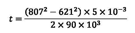
or t= 7.4 milliseconds. This means that drive electronics must act very quickly in order to protect the DC bus caps.
From the above, one of the constraints inherent to brake chopper circuitry should be evident – the effect of heat. The resistors used to dissipate this energy must be sized based not only on their current-carrying capacity but also on the duty cycle, or the ratio of the time spent conducting per unit time. In ABB’s case, typical cycles available (for stopping duty only) are 3 sec. on/27 sec. off (or 10%); 30 sec. on/180 sec. off (14%); 10 sec. on/50 sec. off (17%); and 60 sec. on/180 sec. off (33%). As could be expected, the longer and/or more often the resistors must conduct, the larger and more expensive they are. While many drives include the circuitry as standard, the resistors are virtually always optional and must be mounted external to the drive itself. Therefore, additional space and supplemental cooling are often needed. Cutting cost by attempting to undersize the resistor can result in fire and property damage and so is clearly not a good idea.
Even with these drawbacks, a brake chopper is typically a less costly investment than a new regenerative drive, and unless used in a safety regulated operation the chopper will work even if main power is lost. Choppers are called for when braking is only needed occasionally; braking energy required is not large; or braking is still required, albeit under the constraints above, in the event of power loss.
Please contact us at info@joliettech.com to learn more, or go to joliettech.com. If you have thoughts or ideas, please share them in our Comments section. And please join us next week for another issue.

Regards,
Jay Baima
Joliet Technologies
Leave A Comment
You must be logged in to post a comment.