As many of you realize, modern pulse-width modulated (PWM) variable frequency drives (VFD’s) can place added stresses on motor insulation systems, particularly in older motors in drive retrofit applications. Let’s examine this type of application in greater detail to understand causes and discuss preventive and corrective measures.
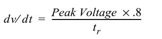
VFD’s output synthesized AC waveforms, consisting of rapid rise-time pulses of varying width (hence the term “pulse-width modulated”). These pulses are generated by the switching “on” and “off” states of the drive output electronics, typically insulated gate bipolar transistors (IBGTs). Each time one of the IGBTs switches on, the output voltage from that device rises rapidly, over-shoots the nominal voltage value, and then settles back down to nominal, which is the rectified DC voltage produced in the drive’s converter stage. This switching on and overshoot happens very rapidly; the “rise time”, defined in NEMA MG-1 as the time required for the voltage to rise from 10% to 90% of DC link voltage, is in the neighborhood of 0.1 microseconds. Rise time is referred to as “dV/dt”, short-hand for the instantaneous rate of change of voltage with respect to time, and the formula is:
This creates a very steep wave front, which due to differences in impedance of the motor cable and the motor itself, can be reflected back if the cables are of sufficient length. These reflected pulses can combine with the drive’s output pulses to increase the amplitude of the voltage seen at the motor terminals. This rise can be made worse if the particular motor and cable characteristics are such that they comprise a resonant circuit; the resonance, sometimes termed “ringing”, adds to the voltage to the point where peaks of greater than twice the incoming line voltage may be produced at the motor terminals. If the motor’s insulation system is older and/or not designed to withstand these higher voltage levels, the insulation can be overcome and winding shorting can occur over time.
To address this concern, many motor manufacturers create insulation systems for motors used with inverters/VSDs to comply with NEMA MG-1, Pt. 31, which requires that motors 600V or less be able to withstand voltage peaks of up to 1600 volts at a rise time of not less than 0.1 microsecond. However, older motors may not be compliant, or the quality of their insulation systems unknown, and as such are susceptible to a higher risk of damage if fed by VSDs. In such cases, there are some measures which can be taken to reduce this risk:
- First, ensure that other mechanical considerations are addressed such that the motor is not subjected to over-heating due to factors such as ambient operating temperature and loading. For example, GE technical data states that anecdotal evidence has indicated that for every 10 degrees C above the rated insulation temperature, insulation life is reduced by 50%.
- Check the quality of the insulation system before installing a VSD. A qualified electrician can perform a time resistance test to assess the stability of the existing insulation. This data should then be discussed with the motor manufacturer to determine whether original manufacturing specifications are maintained. Keep in mind that, even if the motor has been re-wound, it may or may not be in compliance with either original manufacturing specifications or NEMA MG-1 guidelines, so testing is advised.
- Minimize the length of the leads from the drive to the motor. While each case is different, owing to different motor, drive, and cable characteristics, the rule of thumb we use is “as short as practical, but not more than 50 meters”. Where longer than this, or where conditions are more severe, we recommend a drive output filter. Such a filter can consist of a reactor, a more sophisticated reactance/inductance (dV/dt) filter, or a sine wave filter. In a nutshell, all of these devices work to slow the rise time of the voltage pulses and thus reduce the voltage increases seen at the motor terminals. In general, a reactor could be used for motor leads up to 100 meters, and a dV/dt filter to about 500 meters. Sine wave filters allow cable lengths limited only by the cable impedance/voltage drop, but are significantly more costly than the other two options.
I trust that this information has given some guidance when considering installing VSDs to control existing motors. If you have specific case histories or questions, please visit the Comments section or contact us at info@joliettech.com. And as always, remember to visit us on-line at joliettech.com and peruse our blog at joliettech.com/blog. See you next week!

Regards,
Jay Baima
Joliet Technologies
Leave A Comment
You must be logged in to post a comment.