Drive Overload: Typical Variable Speed Drive Faults and How to Troubleshoot Them
Drive Overload faults can manifest themselves in response to rapidly changing load conditions or drive transistor over-temperature, among other causes. Below we discuss these faults, their causes and possible resolutions.
Variable speed drive (VSD) overload faults are intended to trip the drive before significant damage to internal components occurs. Various manufacturers have different means of monitoring drive loading and issuing faults when anomalies occur, depending on programming. Let’s examine what can trigger these faults, and how they can be corrected.
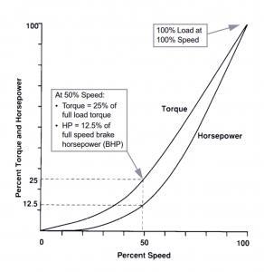
Overload faults can be generated in response to loading which exceeds the rated capacity of the VSD, or to user-programmed settings customized for the application. The first instance simply means that the rated current-carrying capacity of the VSD is being exceeded by a percentage and/or for a time greater than the specifications indicate, which can result in drive overheating and, ultimately, damage to internal components. Most drives are manufactured with a specific overload rating, in percent of rated output current and for a specific amount of time. For example, a VSD rated for what is termed “normal duty” might have an overload rating of 120% of rated output current for 60 seconds. This overload rating allows for increased electrical draw during starting while maintaining the drive’s power components at or below specified temperature. It also is used to properly size VSDs based on motor full-load amperage and type of load profile. “Normal duty” drive ratings are used for loads with speed/torque ratios which are quadratic; they require relatively low torque at low speeds, while the torque increases rapidly at higher speeds (see Fig. 1). This type of load profile is also referred to as “variable torque”, and is typical of centrifugal fans and pumps.
© Schneider S.A.
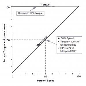
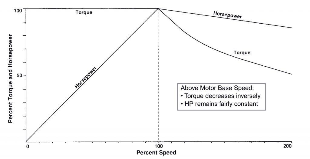
“Heavy duty” drive ratings are used for “constant torque” or “constant horsepower” loads. “Constant torque” loads require full torque on starting and throughout the speed range, while “constant horsepower” load torque is very high on starting and drops as speed increases (see Figs. 2 and 3).
© Schneider S.A.
© Schneider S.A.
Drives often have dual ratings; the same 3-phase, 480Vac drive may be rated at 25hp/38 amps output when used for variable torque loads, but only 20hp/31 amps output when used on a constant torque or constant horsepower load. As noted above, the lower “heavy duty” amp rating is meant to allow the drive to handle the higher starting currents of constant torque or constant horsepower loads, then continue to operate at rated current without overheating. Demands which exceed these ratings can cause drive overload faults. This is also why you need to consider not only motor FLA, but also load profile and its required overload capacity, when sizing a VSD.
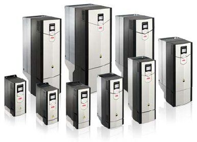
Even when a drive appears rated correctly based on motor FLA and load type, changing environmental or load conditions can overload a drive. We have years of experience in providing drives for the baking industry, largely in mixing applications. Mixers can see a wide variety of batch types, each with different blending characteristics and requirements. And within a given batch, the visco-elastic nature of the dough changes as it blends. This requires a drive capable of handling the rapidly changing torques associated with these changes. Several years ago, many drives were not capable of responding fast enough, and their power sections were overloaded and failures were not uncommon. Modern drives, however, such as ABB’s ACS880 series (Fig. 4; more info here), have rapidly responding control algorithms which can handle these changes easily. ABB uses their proprietary Direct Torque Control (DTC)® to consistently and efficiently accomplish this.
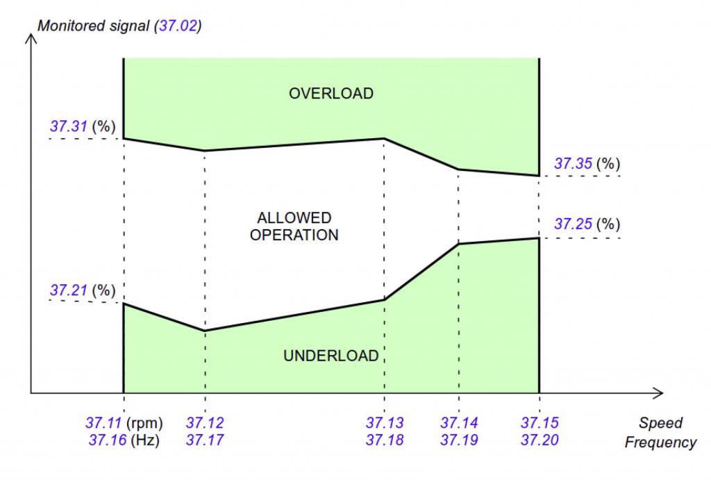
Some VSDs, such as ABB’s ACS880 series, also allow programming of a custom load curve (Fig. 5), which is used to compare motor feedback (torque or current) with drive output reference (speed or frequency) along selectable operating ranges. These custom load curves can be used to detect both overloads and underloads. With respect to overloads, this can be used to detect a clogged pump, for example. The user selects several operating points and assigns high (overload) and low (underload) ranges to each of them. The drive software then interpolates between these points to create a curve. Delay times are also set, which permit out-of-range values for a set period of time before an alarm or fault is issued.
© ABB Inc.
A fault typically means the connected load should be examined for problems, but care should be taken to ensure that curves are properly programmed in the first place; this type of monitoring is of no value if it means the application is repeatedly shut down because of nuisance drive tripping.
Most drives also provide the user the ability to adjust acceleration and deceleration curves. Sometimes these are left at factory defaults, which may or may not be sufficient for the application. One example – it is common for larger diameter fans to require slower acceleration and deceleration to avoid exceeding a drive’s overload rating. If curves are not adjusted, a user might not even be able to commission a drive without seeing an overload fault. Particularly during deceleration, there are two other complicating factors. Trying to decelerate the impeller (load) too rapidly can cause regeneration, during which the connected motor acts as a generator pushing voltage back into the drive and increasing heat build-up (see also our earlier article on over-voltage faults). In other cases, a VSD’s dynamic braking circuitry may be set to inject too much excitation current, stopping the drive too rapidly and increasing the electrical and mechanical stresses on the drive and connected equipment.
High ambient temperature can also compromise a VSD by effectively reducing its ability to dissipate internal heat to protect sensitive electronics. Most drives can operate at their rated outputs up to 40°C/104°F. At a reduced amp output, manufacturers typically allow operation at up to 50°C/122°F. (Specific de-rating formulas for increased temperatures up to rated maximums are provided by each manufacturer.) Note, however, that these temperatures are measured at the drive’s heatsinks, and so are the sum of the ambient air flowing over the drive and the heat the drive generates as it operates. That is why placing a drive in an enclosure requires a careful determination of cooling needs. Every drive generates heat as it operates, and watt loss is roughly 2 – 3% of kW output. (Again, each manufacturer publishes watt loss specifications for their drives, typically in the user manual.) This means, for example, that a 22kW/30hp drive may be shedding 500W of heat into the enclosure. If you’re not using fans to cool the enclosure, and the ambient air around the enclosure is already at, say, 32°C/90°F, the enclosure can heat up very quickly. This situation can be made much worse if your enclosure is outdoors and not sheltered from direct sunlight. And even if you are using the correct size and number of cooling units, their maintenance is also important; a filtered fan cannot properly move air if the filter is clogged. Enclosure cooling companies such as Pfannenberg, Hoffman, Thermal Edge, Noren, and ISC typically provide online tools to help calculate cooling requirements and the equipment needed.
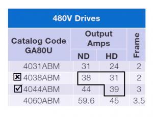
If a drive is experiencing frequent overload faults, an important pre-troubleshooting step is to confirm that it is rated properly for the application. Make sure the drive’s rated output meets or exceeds the motor nameplate FLA. Also, if the load is a constant torque or constant horsepower type, make sure the drive’s overload rating is adequate. For example, assume a motor is pushing an agitator and we want to fit it with a Yaskawa GA800 drive. The motor’s FLA is 37 amps at 460Vac. We should choose the heavy duty rated 25hp drive (#GA80U4044ABM) shown in Fig. 6; even though the normal duty amp rating of the next smaller drive exceeds 37 amps, it will heat significantly more during starting and may fault, either during starting or during run, since it may not have sufficient capacity to allow adequate cooldown at rated amperage (i.e. after starting).
Courtesy Yaskawa America, Inc.
If VSD sizing and specification have been confirmed correct and the drive is still seeing overload faults, the next step is to determine whether the drive’s operating “environment” has changed. First, verify that incoming power to the drive is within specification and hasn’t changed significantly. A five percent sag in supply voltage will appear perfectly acceptable when looking at drive specs, but if the incoming supply voltage is already at five percent below nominal the resultant ten percent below nominal level might be pushing the drive too hard. Next, widen the scope of the investigation. Have higher ambient temperatures in the drive operating area been seen regularly? Are filters on any cooling equipment clogged or past their expected life? Are the drive’s cooling fans relatively dust-free? If a refrigerant cooling system is being used to cool a drive enclosure, is it operating properly, and is condensate properly cleared? Some higher horsepower drives are liquid cooled; is adequate coolant being circulated, at the correct temperature? If the drive enclosure is located outdoors, don’t overlook the obvious – has something changed which increases the cooling demand of the enclosure (e.g. a shelter has failed or been removed). Also, examine the application from several perspectives. Is the motor, and especially the bearings, in good condition? Are any connected components (pulleys, couplings, belts, linkages, etc.) in good working condition and correctly maintained? Has the process changed, and if so, how has this impacted the load on the motor and drive? For instance, in mixing applications viscosity can vary widely among batch types; a crusher might be fed with a different grade of stone; a pump previously used to move surfactant might be re-purposed to push lotion. In these cases, the drive may be being asked to do more than intended when it was originally specified.
If none of the above resolve the situation, it might be time for repair or replacement. Please contact us for any of your drive or motor control needs. If you need information or assistance, email or call us at 866.492.9888. You’ll also find valuable information throughout our site. And if you’d like to share your experiences with our readers, please leave a comment below.
‘Til next time, thanks for reading!

Regards,
Jay Baima
Joliet Technologies
Leave A Comment
You must be logged in to post a comment.