Over the next few columns, we’ll examine some of the more common faults experienced by variable speed drives, their causes, and some ways to resolve them.
Modern variable speed drives (VSDs, a.k.a. VFDs or ASDs) are very reliable devices when installed and maintained properly. However, VSDs can experience faults, alarms, and errors from time to time, just as can any complex electronic component. It is helpful to know how to deal with such issues when they occur. Over the next few columns, we’ll discuss some of the more common faults that might be seen, and how to address them efficiently and with minimal wasted effort. I will be referencing troubleshooting methods recommended by a variety of VSD manufacturers we use, although many of these approaches will be suitable, with minor modifications, for any modern VSD.
Before we begin, let’s cover some general considerations applicable to any troubleshooting process. First, the manufacturer’s manual is usually your best source for determining the problem and what to do about it. Often the manual will have a decision tree or block diagram detailing the specific steps needed to troubleshoot each fault or alarm. This can save many hours of time addressing the problem, and speaks to the wisdom of having up-to-date documentation protected and available for all of your equipment. And keep in mind that this often extends beyond the core equipment manual; a VSD over-voltage fault, for example, might require an evaluation of incoming power quality, for which an accurate one-line diagram and/or other electrical system drawing(s) will be invaluable.
Second, approach the problem in a methodical, step-wise fashion. The goal here is to not confuse the effort by making multiple changes before assessing whether or not the problem is resolved. By executing and checking off steps as you take them, you can clearly identify which step(s) corrected the problem.
Third, whenever possible let the VSD help you pinpoint the problem. Most drives have fault history tracing, which is extremely helpful in narrowing down the issue. This history is usually available via the VSD’s HMI; if the HMI isn’t functioning, the history can sometimes be accessed by connecting the drive to a PC using the drive manufacturer’s software.
Finally, keep in mind that the VSD is part of an overall system, comprised of an incoming power source, the drive itself, a downstream load (motor), panel- or field-mounted controls, and all of the conductors and protective devices interconnecting them. A VSD fault might very well indicate that the drive itself is functioning perfectly by identifying a problem with the power supply or the motor it is controlling.
With the above firmly in mind, we’ll begin looking at some drive faults and the recommended measures for addressing them. Today we’ll examine an overcurrent fault.
Overcurrent (typically shown as “oC” (or similar), or as a hexadecimal code on the drive’s HMI):
An overcurrent fault can occur for a wide variety of reasons. Most are related to problems with the load or connecting cabling, and/or drive parameters not properly set to accommodate the load. Overcurrent problems originating within the drive itself usually don’t happen until after recurring field problems have not been addressed. Here are some typical issues associated with this fault:
- The motor load is too heavy for the drive: Drives are correctly rated based on the amperage they can carry without exceeding their temperature rating. The drive’s rated amperage must meet or exceed the motor’s full load amperage (FLA) as indicated on the motor nameplate, AND the drive’s overload capacity must be able to support the motor’s starting current under normal operating conditions. Because starting current can vary based on the load the motor is driving, most manufacturers list two amperages for a given drive – normal duty (a.k.a. standard duty or, in some cases, light duty) and heavy duty. These duty ratings are intended to reflect the torque required to support the connected loads – normal duty ratings apply to variable torque (also called quadratic) loads such as centrifugal pumps and fans, while heavy duty ratings apply to constant torque or constant horsepower loads such as compressors, positive displacement pumps, presses, drill presses, etc. An example of the difference between these two ratings for several 480V drives from the Yaskawa GA800 series is shown in Fig. 1. Note that the ratings for heavy duty are significantly lower, which simply indicates that when a drive is used for a heavy duty application it will, on average, see more current draw during load changes (startup, rapid accel/decel, etc.) and so will need more headroom to accommodate this.
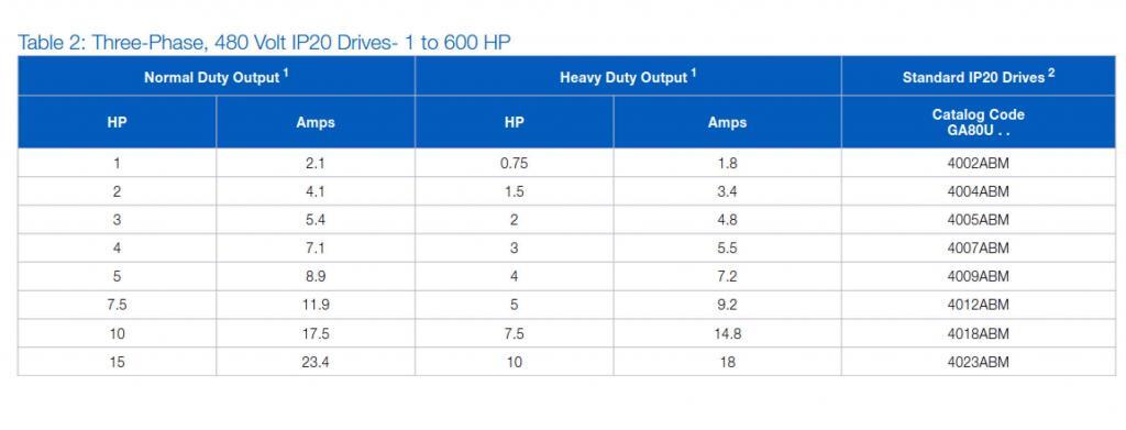
– Courtesy Yaskawa America, Inc.
If it’s confirmed that the drive is sized properly but overcurrent issues remain, other causes should be explored. Measuring the motor’s current draw with a true RMS ammeter is a good first step. This can indicate if the motor needs further examination. Excess current draw can result from motor insulation breakdown (see below), internal short-circuiting, or excessive bearing wear.
- The motor insulation is breaking down: This can result from age, prolonged control by a VSD, overheating, and other factors. An insulation resistance test is used to determine the quality of the motor’s insulation. A full explanation of this type of testing is beyond the scope of this article, but in general, spot reading tests can be valuable if the motor’s insulation resistance history is available, and time vs. resistance testing is better if no history of motor insulation resistance has been recorded. (See Fig. 2 for an example of time vs. resistance test results.) The key here is to have this testing done by qualified personnel; there are many variables which can influence the testing and reduce its accuracy and so must be taken into consideration.
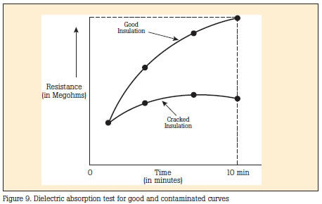
– Courtesy ColeParmer
Insulation breakdown is usually corrected by rewinding or replacing the motor. It is helpful to know why the breakdown occurred in the first place to see to it that the same cause(s) don’t reduce the “new” motor’s life as well. One such cause is due to the inherent design of insulation systems in older motors. Many older motors are not able to effectively withstand the voltage spikes seen at the motor terminals when controlled by a VSD for prolonged periods. These spikes result from the VSD’s rapid output pulses used to create the synthesized AC waveform sent to the motor. They are inherent to most modern drives and can only be reduced by using output filters. Just how much they increase voltage levels at the motor terminals is determined by the capacitance of the drive, motor leads, and motor; the length of the motor leads; the drive’s pulse rise time and switching frequency; and the presence or absence of the aforementioned output filters. Suffice to say that it is not uncommon to see voltage levels of 2 – 4 times the line (input) voltage level at the motor terminals when a VFD is used. This is why motors suitable for being controlled by a VFD are typically built to standards such as North America’s NEMA MG 1 Parts 30 & 31, which requires motor insulation systems to be built to withstand at least 3.1x the motor rated voltage (for ≤600V motors) or 2.04x the motor rated voltage (for >600V motors). In practice, it is not uncommon to see manufacturers such as GE build 460V motors with 1800V (or higher) insulation systems. Such systems were generally not available in older motors, so even those with relatively intact insulation systems may not be able to withstand drive-induced voltages for long periods.
Motor overheating is another major cause of VFD overcurrent faults. This can be the result of the over-voltage effects mentioned above, which can gradually heat up terminal end windings. It can also be the result of operating the motor in high ambient environments. Additionally, operating a self-cooled motor (e.g. a totally enclosed fan-cooled design) at low speeds continuously can cause the motor to heat up due to reduction of air across the cooling fins. This is why it is recommended to not run fan-cooled motors at less than about 60% of rated speed for extended periods, even though a drive certainly allows this. It is widely recognized that for every 10 degrees C increase in winding temperature above the motor rated ambient, motor life is reduced by 50%. While there are a lot of factors affecting the accuracy of this statement, it remains true that motor life is reduced by overheating. So what to do about motor overheating? Taking care of the easiest things first, determine the range of operating temperatures the motor is exposed to, and see what can be done to reduce the excessive ones. Then, if you find that your self-cooled motor is running too slowly, see whether your process can handle an increase in motor speed (or replace the motor with one with a lower rated speed, if that’s economically feasible). Separate blower systems for motor cooling can also be installed (see Fig. 3), and gear reduction may be another option depending on cost and space constraints. Finally, if you’ve addressed all of these issues and find the problem remains, make sure you test the motor thoroughly to determine if a rewind or replacement is needed.
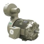
– Courtesy General Electric
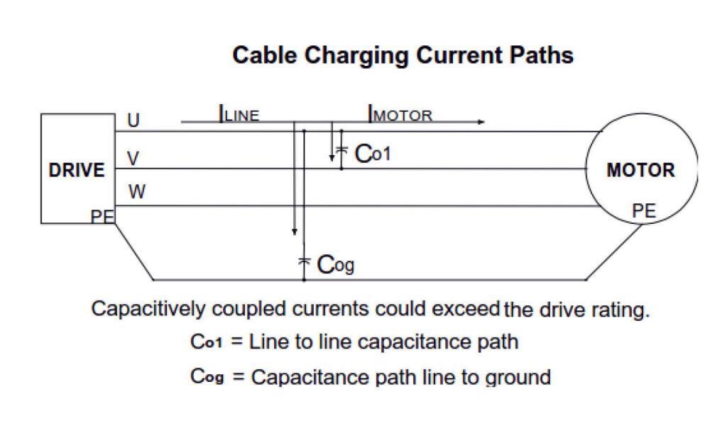
- Motor lead insulation is breaking down: The impact of this may be obvious – a phase-to-phase or phase-to-ground short circuit that trips the drive and, perhaps, upstream protective devices. In the process, the drive’s output section may be permanently damaged, depending on the timing and location of the short. The VFD will see weakening insulation as an increase in current leakage, placing additional stress on the drive output. Overcurrent faults can be the result. In some cases, particularly where proper grounding and shielding methods are not followed, the leakage current can also affect nearby wiring and/or components through capacitive coupling (See Fig. 4). Cable insulation testing is a good, but often ignored, tool in a solid preventive maintenance plan. Done correctly, it will reveal impending problems without damage to the cable or unpredictable downtime. In any case, replacing the cable is the only option.
- Drive settings may not be appropriate for the application: Factory-default drive settings aren’t always correct for the application. Preset acceleration/deceleration profiles may not be correct. For instance, if the acceleration is programmed to be too rapid for the torque needed, the drive may see excessive current inrush. The same can occur during rapid deceleration of high inertia loads. Some drives also allow setting of custom V/f (volts/hertz) patterns to permit the drive output to be tailored to the load torque profile, although this can involve significant trial and error. Again, incorrect settings can cause overcurrent faults. Flux vector drive algorithms were developed to circumvent this problem by carefully modeling the motor and adjusting drive settings during field setup. Whether or not vector control is suitable depends entirely on the application. To address this cause of overcurrent, adjust accel/decel and control parameters as the application allows until the fault is resolved. If it cannot be resolved, and the other potential causes of overcurrent have been addressed, then the problem might be a short in the drive output. Alternatively, it could be that a drive with a higher rated output is needed; in some applications, exceptionally high starting torque might mean that the usual heavy duty rating of 150% of FLA isn’t sufficient, and the next higher rated drive is needed. Extruders and presses can be examples of this.
- Dynamic braking for rapid deceleration is too aggressive: Large, high-inertia loads such as chippers, grinders, centrifuges, and even some large diameter fans can take several minutes to completely coast to a stop if not actively braked. Drives typically use current injection – sometimes referred to as dynamic braking or flux braking – or stepped frequency changes to decrease motor stopping time. An illustration of dynamic braking for the Yaskawa A1000 drive is shown in Fig. 5. If the parameters that govern the chosen braking method aren’t set correctly, overcurrent faults can occur. A lot of this is trial and error; loads can change depending on the application, and it may take some experimenting to determine the best settings to use under the range of normal operating conditions.
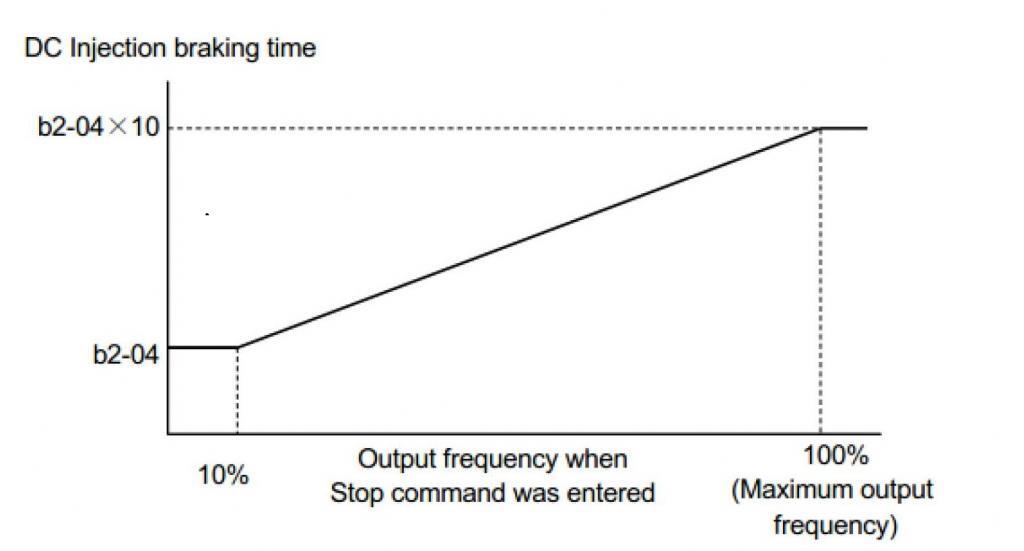
– Courtesy Yaskawa America, Inc.
- The drive is issued a Run command while the motor is coasting, and Speed Search is not enabled: While the motor is coasting to a stop it retains considerable inertia. If a Run command is sent during coasting, the drive can experience an increase in current through the DC bus. Many drives have an internal setting to “catch a flying motor”; i.e. determine its speed and match it with the drive’s output. By carefully controlling the current, an overcurrent fault can be avoided. Activating this function is typically a matter of adjusting a few parameters, and it is dependent to some extent on the control method selected (V/f, open loop vector, or closed loop vector). Changing load conditions can also mean that some trial and error is needed to get the settings correct.
While there are a number of other causes for overcurrent faults, the above make up a large percentage of them. Next time, we’ll look at overvoltage faults, their causes and means for addressing them.
Are drive faults keeping you up at night? Joliet Technologies has the knowledge and experience to assist you with any of your drive problems. Call us at 866-492-9888, learn more about our capabilities on our Services page, or email us. And be sure to check back next time as we explore more trouble-shooting solutions.
Thanks for your time!

Regards,
Jay Baima
Joliet Technologies
Leave A Comment
You must be logged in to post a comment.