Adjustable Speed Drives –
(a.k.a. Variable Speed Drives)
What They Are, How They Work
Application Information
- Adjustable Speed Drives – Application Information
- DC Drives – Principles of Operation
- DC Drive Types
- DC Motor Control Characteristics
- AC Drives – Principles of Operation
- AC Controller Types
- AC Motor Control Characteristics
- Motor Selection
- AC vs. DC Drive Comparison
- Basic Mechanics
- Other Application Factors
- Measuring Machine Torque
- Mechanical Formulas
AC MOTOR CONTROL CHARACTERISTICS
The synchronous speed of an AC induction motor is directly proportional to the applied frequency.
| Speed = | 120 x Frequency |
| No. of Motor Poles |
The synchronous speed is the speed of the rotating electrical field, not the actual motor rotor speed. The difference between the synchronous speed and the full-load motor speed is called slip, which is normally expressed in percent.
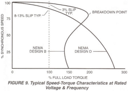
The percentage of slip is determined by the design of the motor, primarily the rotor resistance. NEMA has assigned code letters (A, B, C, D, etc.) to standardize motor characteristics including slip. The type most commonly used is NEMA Design B with 3% slip at rated operating conditions. Figure 9 shows typical speed/torque curves for NEMA Design Band D motors.
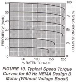
As the applied frequency is changed, the motor will run faster or slower as shown by Figure 10. The actual full-load motor slip (as a percent of the motor synchronous speed) varies in inverse proportion to the frequency, where a 3% slip motor 60 Hz would have a 6% slip at 30 Hz or 1 1/2 % slip at 120 Hz. Motor speed is limited only by the maximum inverter output frequency, load torque requirements, and the mechanical integrity of the motor.
Adjustable Speed Drive Application Information provided by: FINCOR Automation


