PLEASE NOTE: Effective 2019, we no longer supply Control Techniques variable frequency drives and components. We have drives from several other manufacturers which can meet or exceed the performance characteristics of the Control Techniques line. Simply complete the form below, or contact us with the model of your current or obsolete Control Techniques drive and we’ll be glad to identify a suitable replacement.
Also, the Fincor and Saftronics lines of AC variable frequency drives, DC variable speed drives, and reduced voltage starters were once owned by Emerson but have been obsolete for several years. However, we have many years’ experience working with these drives and can quickly identify replacements capable of exceeding the quality and performance of these older drive technologies. For a suitable replacement, fill out the form below or contact us with your drive or application requirements, and we’ll handle it from there!
- Overview / Typical Applications
- Features, Ratings, Prices & Ordering
- Terminal Diagram and Description
- Specifications and Dimensions
- Options – Overview / Drive Configuration and Programming
- Communication / Operator Interface
- Power Accessories
- Input / Output & Communication
Input/Output
BI-POLAR ANALOG INPUT CARD (SE51)
The bi-polar speed reference input card (SE51) allows the direction of a motor to be controlled via a speed potentiometer or external bi-polar speed reference rather than the forward / reverse terminal selector. The +10V potentiometer reference can be supplied from the drive (term. #3) or from an external power supply. The -10V potentiometer reference must be supplied from an external supply. The SE51 also has a relay that is controlled by the digital output (default “zero speed”) of the drive.
SE51 TERMINAL DIAGRAM
| NOTE |
| |
| For complete instructions. refer to the Commander SE User Guide or go to www.emersonct.com |
SE51 TERMINAL DESCRIPTION
| Singular Connector | Pin # | Function |
| PL1 | 12 | Bi-polar Analog Input (+10 VDC, 22k Ohms) 0V Common |
| PL2 (Interface connections to Commander SE) | 1 2 3 4 5 6 | 0V Common 0 to + 10 VDC Analog Output +24 VDC Supply for option card Digital Input (+24 VDC) to control relay Run Forward Output (+24 VDC)* Run Reverse or Run Forward / Reverse Output (+24 VDC) |
| PL3 | 12 | Relay Contact Common (48 VAC / DC, 2A resistive) Relay Contact (Normally Open) |
| * Directional control of Commander SE |
Information provided by Control Techniques, a world leader in the design, production and marketing of electronic drives for the control of electric motors.
Communication
COMMUNICATION CARDS
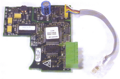
Each fieldbus interface for the Commander SE is a single option card that fits within the drive, Parameter data is transferred to and from the Commander SE using a 2-wire RS485 link into the serial communications port on the drive.
| Communication Protocol* | Order Code |
| RS485 / Modbus RTU | as standard |
| PROFIBUS-DP | SE73 |
| INTERBUS | SE74 |
| DeviceNet | SE77DN |
| CANopen | SE77CO |
| * Maximum communication rate through RJ45 port is 192 kbaud Commander SE operates as slave node only |
Information provided by Control Techniques, a world leader in the design, production and marketing of electronic drives for the control of electric motors.


