Preventive Maintenance Tips to Extend the Life of Your Variable Speed Drives
Variable Speed Drives (VSDs) are critical to modern industrial operations, delivering precise motor control, energy efficiency, and process flexibility. Yet, like any advanced equipment, their long-term reliability hinges on a disciplined preventive maintenance program. Proactive care not only safeguards your investment but also minimizes costly downtime and extends the operational lifespan of your drives and connected motors.

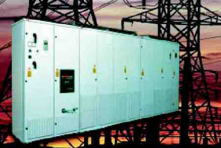
Fan Injecting Dust into Drive Enclosure
Technical Discussion: Essential Preventive Maintenance Actions
Establishing a robust preventive maintenance schedule is the foundation for maximizing the performance and longevity of your VSDs. Focus on these key actions:
- Maintain a Clean Environment: Dust, debris, and moisture are among the primary threats to VSD electronics. Regularly inspect and clean enclosures, filters, and cooling fans. Ensure all ventilation paths are unobstructed.
- Monitor Temperature and Cooling: Overheating is a leading cause of premature drive failure. Verify that ambient temperatures remain within manufacturer specifications, and promptly replace failed fans or clogged filters.
- Check Electrical Connections: Loose terminals or corroded wiring can lead to erratic operation or damage. Tighten and inspect all power and control wiring during scheduled outages.
- Inspect for Component Wear: Capacitors and relays degrade over time. Look for signs of bulging, leakage, […]