At Joliet Technologies, one of our strongest markets is the direct current (DC) motor and motor controls field. There remain a significant number of DC motor applications in the utilities, transportation, and manufacturing sectors, including among others the oil, pulp and paper, metals, and automotive industries. While many are familiar with typical alternating current (AC) variable frequency drives, DC drive applications are less common. However, the basic operating concepts share some common elements. Let’s examine DC drive basic operating principles in more detail. Some of the information which follows is excerpted from Siemens online training, which can be accessed here: Siemens Online Motors and Control Courses.
Most commonly, DC drives are used to regulate the speed of shunt wound or permanent magnet DC motors. In larger motor applications typical to industry shunt wound motors are used, and we will refer to those for purposes of this discussion. In shunt wound motors, the stator pole pieces are electromagnets wired in parallel with the armature (rotor) windings. Typically, voltage is supplied to the stator poles via a separate source of supply (referred to as a field exciter). This creates a magnetic field, called a shunt field, in the stator. When the drive supplies voltage to the armature windings, the resulting current produces a magnetic field in the armature as well. Simply put, it is the interaction of the shunt and armature fields which result in the torque needed to rotate the armature.
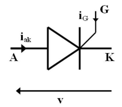
The heart of the DC drive is the converter section, which rectifies supplied AC voltage to produce variable DC voltage to supply the armature. Rectification is commonly accomplished via thyristor bridge, with two thyristors connected in series per phase, for a total of six thyristors. The thyristor is effectively a diode “switch” with a controllable gate; the gate (G) provides current to switch on the thyristor, which conducts as long as the anode (A) remains positive to the cathode (K):
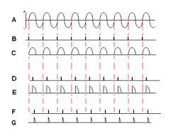
Gate current is applied to the incoming sine wave at a point along each half cycle (i.e. phase angle) specified by the drive controller. The earlier in the cycle the gate fires, the longer the thyristor remains “on” (i.e. conducts), which results in a higher average voltage output by the rectifier. This can be seen in the following graphic; “A” being the incoming AC sine wave, “B”, “D”, and “F” the gates firing at progressively later times, and “C”, “E”, and “G” the resulting DC voltage level out:
Voltage level is calculated as:
As such, the highest average output from a 460VAC input would be a rectified 621 volts DC. This voltage is adjusted by controlling the firing timing (i.e. the gating angle) of the thyristors, and is then supplied to the armature to control motor speed. Note that drive parameters must be set to ensure that the output voltage does not exceed the rated nameplate voltage of the motor, typically 500VDC for a 460VAC supply.
The motor draws current from the drive proportional to the amount of torque needed to drive the load. At base speed and no load, very little armature current is needed, and so less voltage is output to the armature by the drive. For example, at no load the gating angle might be something like 45°, which translates to ~440VDC output. Once load is introduced, the voltage level in the armature must increase to maintain speed, and the thyristors are fired earlier to compensate – an angle of ~36° produces nameplate rated voltage of 500VDC.
DC drives have far more functionality than the basic operational concept above describes, but that functionality will need to wait for another column. In the meantime, please “fire” off any questions, thoughts, etc. (and don’t worry about the phase angle!) in our Comments section, or send them to info@joliettech.com. There is much more information on our web site as well, so stop by for a visit (joliettech.com) or call us at 815.725.9696. And please tune in next week for another issue. Have a great week!

Regards,
Jay Baima
Joliet Technologies


Leave A Comment
You must be logged in to post a comment.