How to Calculate Forced Air Cooling for Control Panels – A Simple Formula for Longer Lasting Controls
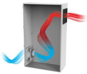
Most people are aware that electrical and electronic components are heat-sensitive, and that their life expectancies can be reduced significantly if they are not kept within specified operating temperatures. Typical upper limits for specified operating temperatures are 40°C (104°F); occasionally 50°C (122°F). One common application challenge is maintaining temperature below these upper limits within a control enclosure. There are a number of variables which need to be considered when determining the cooling needed, including the size of the enclosure, its material and finish, its location (e.g. outdoors in shade or sun), and, in general, the variability of the ambient temperature during operating periods. Note that all of these factors are in addition to the the impacts of the internal components and their heat loads; i.e. the heat they give off during operation. Today we’ll examine these factors and look at one cost-effective means for addressing them – forced air cooling, also known as fan-forced air (FFA) or forced convective cooling.
First, let’s look at the formula to calculate the amount of forced air cooling needed. This formula […]
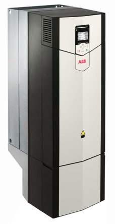 Fig. 1 – Drive Module (ACS880 series) Courtesy of ABB Inc.