Is a Variable Speed Drive Right for You?
There are a number of things to consider before deciding if a variable speed drive (VSD) is right for your application. These considerations can be roughly assigned to one of three groups: energy usage, process/application, and hardware.
Energy Usage:
With the rising cost of electricity and increasing demands on aging power grids, there are large incentives to reduce power consumption wherever possible. According to US Department of Energy statistics, electric motors consume approximately 68% of industrial energy usage, and a significant majority of these could see energy reductions when controlled by VSDs. Couple this with the fact that nearly 96% of the total lifecycle cost of motor ownership is electricity consumed, and you can see that there can be real cost benefits to VSD use.
There are numerous sources online to assess VSD energy savings. For tools to estimate the energy savings your application might realize, go here or here.
Process/Application:
If the process or application you are considering uses a motor to drive a variable torque load (also referred to as a quadratic torque […]
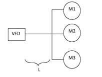 A: The most important consideration in the case of multiple motors connected to a single drive is the length of the leads between the VFD and the point of common connection of the