Uncategorized

Variable Speed Drive Q & A

Many of you have written in with questions regarding installation methods, drive technologies, operating parameters, and other issues. Since it is often time-prohibitive to respond individually to all of them, I thought I would consolidate and address some of the more common – and commonly applicable – questions that have been submitted.

  • “Does the wiring between the VFD and motor require special cabling?
    Can we just use standard 600V wiring such as THHN, THWN, etc.?
    We come across cables that are noted as “VFD rated”. Are these cables required for all VFD installations?”

Drive manufacturers typically recommend shielded, symmetrically constructed cables to reduce the impacts of electromagnetic interference and capacitive coupling. In cases where compliance with European (CE) electromagnetic compatibility is required, these types of cables, properly installed and bonded, are mandatory. Where EU compliance is not a concern, the suitability of the cable used will depend on several factors, including cable length, sensitivity of nearby components and equipment to radiated interference, motor size, and installation methods. Typically, motors rated less than 40 hp, and less than about 100′ of lead length (per phase), can be fed with 600V single conductor […]

By |2020-05-07T10:55:37-05:00May 23rd, 2012|0 Comments

Variable Speed Drive (VSD) Features Explained

Modern variable speed drives (VSDs) are equipped with a multitude of features to provide programming flexibility, enhance efficiency and increase the accuracy of control. Let’s dissect some of these features, typified in this case by the A1000 series of industrial AC drives from Yaskawa (www.yaskawa.com).

Control methods: the A1000 provides up to seven different control methods to suit specific motors and applications. Methods range from basic scalar (volts/hertz, or V/f) control, which adjusts frequency and voltage output in direct proportion based on command reference, through open-loop vector control, to closed loop vector control. Vector control essentially “splits” the stator current into separate torque and field components, analogous to the separate armature and field components of a DC motor, and controls VSD output by regulating voltage magnitude, angle of displacement, and frequency. In open loop systems, modeling is used to calculate vectors and adjust output based on measured output current, while in closed loop configuration, sensors such as encoders or tachometers directly measure rotor position and speed and are able to control output even more tightly. In the A1000, V/f control can provide a typical speed control range of 40:1, while open-loop vector can achieve 200:1 […]

By |2022-10-21T15:16:35-05:00May 16th, 2012|0 Comments

Variable Speed Drives – Motor Cabling Considerations

Much has been discussed of the additional stresses that variable speed drives (VSD’s) can place on motor leads and insulation systems. However, in all but the most sensitive of installations, and assuming the use of properly rated motors, preventive or corrective measures are readily applied, especially during design and engineering stages. While each VSD and motor manufacturer has specific requirements for cabling design and installation practices, there are several elements common to all.

  • Limiting motor lead length: by installing drives as close as practical to the motors they control, the magnitude of voltage overshoot is reduced, lessening the risk of over-voltage at the motor terminals (all other things being equal). There is a length, generally referred to as the critical length, beyond which the magnitude of reflected voltage pulses increases to the the extent that motor insulation systems can be affected. Critical length varies based on cable and drive characteristics and is calculated as:
Critical cable length formula using propagation factor and rise time
Critical Length Formula

The critical length is a consequence of the rate of travel of the pulse from the […]

By |2022-10-21T15:15:35-05:00May 9th, 2012|0 Comments

DC Variable Speed Drive Basics

At Joliet Technologies, one of  our strongest markets is the direct current (DC) motor and motor controls field. There remain a significant number of DC motor applications in the utilities, transportation, and manufacturing sectors, including among others the oil, pulp and paper, metals, and automotive industries. While many are familiar with typical alternating current (AC) variable frequency drives, DC drive applications are less common. However, the basic operating concepts share some common elements. Let’s examine DC drive basic operating principles in more detail. Some of the information which follows is excerpted from Siemens online training, which can be accessed here: Siemens Online Motors and Control Courses.

Most commonly, DC drives are used to regulate the speed of shunt wound or permanent magnet DC motors. In larger motor applications typical to industry shunt wound motors are used, and we will refer to those for purposes of this discussion. In shunt wound motors, the stator pole pieces are electromagnets wired in parallel with the armature (rotor) windings. Typically, voltage is supplied to the stator poles via a separate source of supply (referred to as a field exciter). This creates a magnetic field, called a shunt field, […]

By |2022-10-21T15:14:39-05:00May 2nd, 2012|0 Comments

Variable Speed Drives and Motor Insulation

As many of you realize, modern pulse-width modulated (PWM) variable frequency drives (VFD’s) can place added stresses on motor insulation systems, particularly in older motors in drive retrofit applications. Let’s examine this type of application in greater detail to understand causes and discuss preventive and corrective measures.

VFD’s output synthesized AC waveforms, consisting of rapid rise-time pulses of varying width (hence the term “pulse-width modulated”). These pulses are generated by the switching “on” and “off” states of the drive output electronics, typically insulated gate bipolar transistors (IBGTs). Each time one of the IGBTs switches on, the output voltage from that device rises rapidly, over-shoots the nominal voltage value, and then settles back down to nominal, which is the rectified DC voltage produced in the drive’s converter stage. This switching on and overshoot happens very rapidly; the “rise time”, defined in NEMA MG-1 as the time required for the voltage to rise from 10% to 90% of DC link voltage, is in the neighborhood of 0.1 microseconds. Rise time is referred to as “dV/dt”, short-hand for the instantaneous rate of change of voltage with respect to time, and the formula is:

By |2022-10-21T15:13:36-05:00April 25th, 2012|0 Comments

Reduced Voltage Starters (Soft-starts) – Applications and Benefits

Recent posts have dealt in detail with variable speed drives and their application, but there is another method of motor control capable of providing electrical and mechanical benefits at a lower capital cost – the reduced voltage starter. The three most common types of reduced voltage starter are:

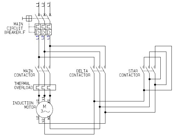
  • Wye/delta: this starter consists of three contactors – main (for isolation); wye (lower voltage for start); and delta (higher voltage for run) – which provides for initial starting of the motor via a wye (“star”) connection, then a timed transition to a “delta” connection to produce motor full-rated speed. The wye connection provides for 58% of line voltage (V-line/1.73) across each winding, and since current varies as the square of the voltage and torque is proportional to current, current and torque are reduced to 33% during starting. A simple schematic is below:
Star-delta motor control schematic
Star-delta Motor Control Schematic
  • Auto-transformer: in this method, an autotransformer supplies the motor via adjustable tap settings (typically 50%, 65%, and 80% of line voltage). This results in reduction in current at the motor terminals by the […]
By |2022-10-21T15:12:18-05:00April 18th, 2012|0 Comments

Variable Frequency Drives (VFDs) and Motor Noise

By their nature, motors generate noise during operation. Because of differences in design and fabrication, even motors of equivalent frame size and horsepower may operate at different noise levels. The amount of noise produced can be affected in a number of ways when the motor is controlled by a Variable Frequency Drive (VFD). For instance, operating the motor at a lower speed will usually reduce noise level, all other factors being equal. Also, owing to a given motor’s design/construction, there may be frequencies, termed resonant frequencies, at which increased vibration and noise are created. Finally, the VFD’s switching frequency affects the amount and quality of harmonic current the drive produces; this current can create additional motor vibration and result in increased acoustic noise. Let’s look at these circumstances in more detail and discuss what can be done to address the noise produced.

Operating the motor at reduced speed is basically self-explanatory; cooling air speed and friction are reduced, resulting in less noise created. That said, a given motor may experience increased vibration at characteristic frequencies, which can increase noise to a level greater than that produced at base (i.e. rated) speed. […]

By |2023-05-04T15:53:28-05:00April 11th, 2012|0 Comments

Variable Speed Drive (VSD) Enclosure Types and Component Protection

Last week we discussed some of the potential impacts of temperature and humidity on the operation and longevity of variable speed drives (VSD) and other motor control equipment. Providing the proper enclosure for the equipment is critical in ensuring you get the most from your investment. Let’s examine the various environmental conditions under which these electronic components might be installed and some methods for protecting against their deleterious effects.

At Joliet Technologies, we are frequently requested to assemble control cabinets for installation in diverse industrial and/or outdoor locations. We have also built panel assemblies for the off-shore oil industry, where the marine environment places extreme demands on the equipment. In designing these assemblies, we pay particular attention to the following:

Ambient temperature: as noted last week, drives and other control components are designed for operation within a temperature range. Typically, it is the upper end of that range, most often 40°C, that is of concern. Operating in an environment above that range places greater stresses on switching devices, potentially decreasing their operating life. If the ambient temperature surrounding the enclosure is sufficiently cooler than the drive enclosure, then either passive conduction or […]

By |2022-10-21T15:09:35-05:00April 4th, 2012|0 Comments
Go to Top